Project - Speed Control of a Direct Current (DC) motor
Objective:
In this project a simulink model for the DC motor will be first devloped per the schematic in figure1
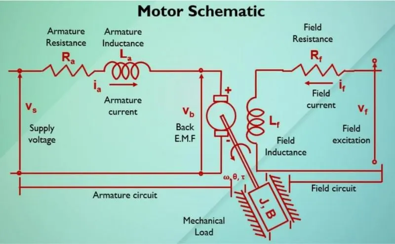
use the proportional , integral and derivative (PID) control design knowledge gained in the training developrd and test a controller to maintain a desire speed for the motor
Key Highlights:
Mathematical modeling from the first principle
modeling an electrical engineering system
Simnlink bassed modeling
control low design and test
Stability of a dynamic system
Deliverable:
MATLAB script to define modeling and control design parameter simulink model to simulate and verify the design.
ANS)
In this project we are building a DC motor in two cases
Case-1: DC motor without controller
Case-2: DC motor with the controller
Firstly we design a DC motor with mathematical equation . Here I am talking the circuit digram of a dc motor which is given in the project objective
Define :
A DC motor is an electrical machine that converts electrical energy into mechenical energy . In input electrical energy is the direct current which is transformed into mechenical ration
J = moment of inertia of the rotor
B = Damping cofficient
Ra = armature resistance
LA = armature inductance
Vb = Back EMF constant
Kt = motor torque constant
V = supply voltage
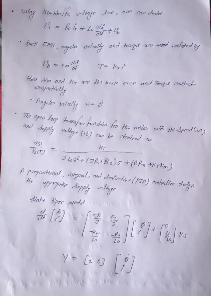
Motor torque T = Kt*l
Back EMF Vb = Kb*w = K
case 2)
What is PID controller.
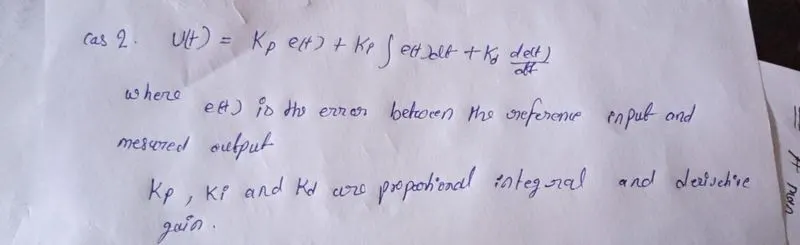
A proportional integral derivative controller (PID controller) is a control loop machanism employing feedback that is widely used in industrial control system and a varity of other application requiring continuously modulated control the proportional integral derivated controller produce an output which is the combination of the output of proportional integral derivative controller . the feedback from the point whichever is a controllable parameter is given as input to the PID controller and the procesed error is minimized to get the desire output if turning of the parameter is done optimally the mathematical PID controller can be defined by the following equation
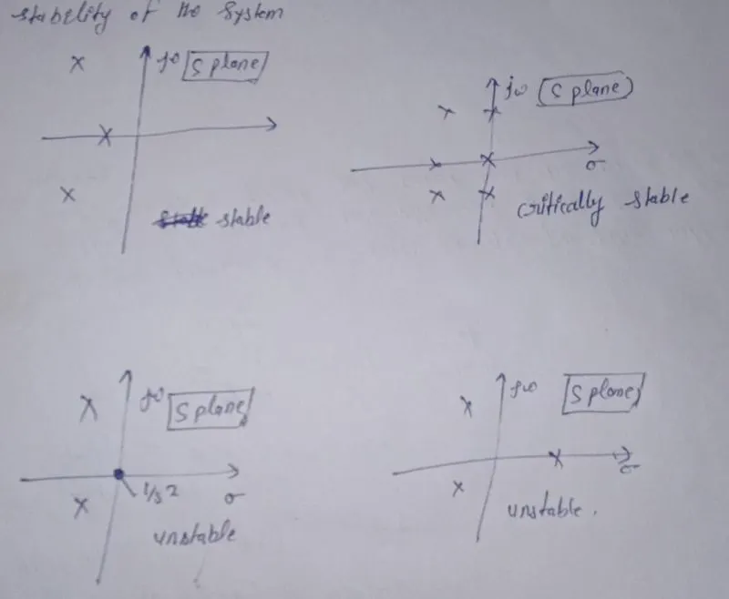
Stability of the system
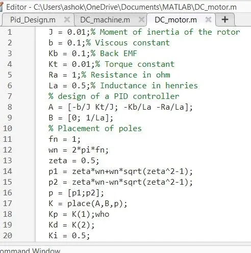
after making the m. script file
we model on the simulink
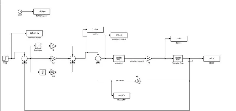
we used a some block in this model
like
. clock
. to workspace
.integrator
derivative
.step function
.gain
.sum
.Transfer function
Model Explanation:
For building the DC motor with PID controller simulink model we use the simulink primitive blocks . firstly we took a clock and a to workspace block that is connected to each other . then for a referenace speed we rook a step input with a step size of 1 and final value 1 . then it was connected to a sum block which is having two input port positive and nigative . the positive input port has a step input and negative port is connected between the integator and to workspace named 'w' . Then the ouput of the sum block is given to a controller gain blocked named as Kp. for the integrat Ki a gain block is used with intial condition as zero . for the derivative gain we are taking a derivative block connected to a gain block named Kd and all the PID gains output is connected to a sum block with positive port . then its output is a given to another sum block positive port and the positive port is connected to the back emf gain block . And its input is taken from the second transfer output as a feedback signal . the second sum block output is given a transfer function having impedance and reistance values and its output is multiplier witha gainn block which is torque constant Kt by multiplie the Kt and transfer function we get torque as output and is given to another transfer function then the output is a speed and it is given to the workspace block . this simulation is run for 10.0 second and the system response is verifyed by plotting the grapf between thime Vs speed and ref_speed.
after build a simulink model
we see the all result
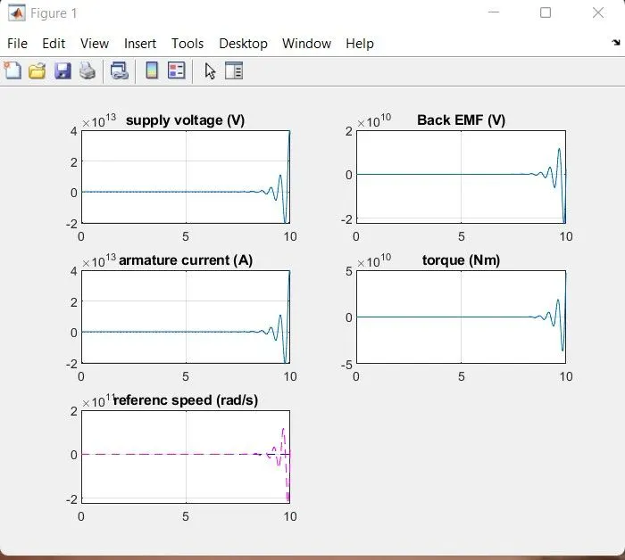
In the above plot we can observe the reference speed plot. The speed is controller by PID controller and match with the reference wave . In this plot the study state error
Overshoot and rise time condition are satisfy . the best response of overall threerest
Conclusion :
The DC motor without control and with control is design and its plot response is observe . the controller is tested under various values of controller gains . the best response is test 3 and it satisfy the condition.