Project - Speed Control of a Direct Current (DC) motor
J= Moment of inertia of rotor
B=Damping constand
R=Armature resistance
L=Armature inductance
Vb=Back EMF constant
Kt= Motor torque constant
V= voltage
motor torque T=Kt*I
Back EMF Vb=Kb*w=Kb*dθ/dt
Applying Kirchhoff's closed loop lawwe get
L dI/dt+ RI=V-kb dθ/dt (a)
applying Newton's Law
we get
J (d^2θ)/dt^2)+B (dθ/dt)=kt*I (b)
converting the above equations to s domain
Ls I(s) +R I(s)=V(s)-kb s θ(s) (c)
I(s)[Ls+R]=v(s)-kb s θ(s)
I(s)=[V(s)-Kb s θ(s) ]/Ls+R (d)
J*s^2 θ(s)+B sθ(s) =KT*I(s) (e)
w(s)=s θ(s) =KT*I(s)/Js+B (f)
substitute I(s) value in equation (e)
J *s^2 θ(s) +B s θ(s) =KT* (V(s)-Kb s θ(s))/Ls+R (g)
s θ(s) [(Js+B)*(Ls+R)]=KT V(s)-KT*Kb s θ(s)
sθ(s)[(Js+B)*(Ls+R)]+KT*Kbsθ(s)=KT*V(S)
Sθ(s)[(Js+B)*(Ls+R)+(Kt*Kb)]=KV(s)
Transfer function output angle θ(s) to the input voltage V(s) given by
Ga(S)=θ(s)/v(s)=KT/s[(Ls+R)(Js+B)+KT*Kb] (h)
transfer function of angular velocity w(s) to the input voltage V(s) given by
Ga(S)= w(s)/V(s)=KT/[(Ls+R)(Js+B)+KT*Kb (i)
di/dt=-R/L*I+1/L*V-Kb/L*dθ/dt
di/dt=-R/L*I+1/L*V-Kb/L*w
dw/dt=-B/J*w+1/J*KT*I
Y(t)=w=dθ/dt
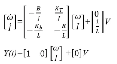
a state space representation of the DC motor from above equation
J=0.01;% inertia
b=0.1; % friction
Km=0.01;% back emf
Kt=0.01;%torque
Ra=1;% resistance
La=0.5;%inductance
A=[-b/J Kt/J;-Km/La -Ra/La];
B=[0;1/La];
fn=1;
wn=2*pi*fn;
zeta=0.5;
p1=-zeta*wn+wn*sqrt(zeta^2-1);
p2=-zeta*wn-wn*sqrt(zeta^2-1);
P=[p1;p2]
K=place(A,B,P)
P =
-3.1416 + 5.4414i
-3.1416 - 5.4414i
K =
38.3133 -2.8584
>> Kp=40
Kp =
40
>> Kd=2
Kd =
2
>> Ki=55
Ki =
55
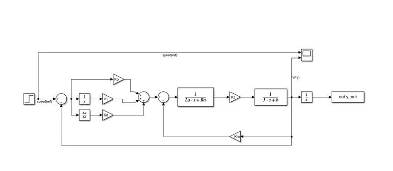
stability of the system can be find by using pzmap
k_dc=1;
s=tf('s');
G1=k_dc*wn^2/(s^2+2*zeta*wn*s+wn^2);
pzmap(G1,'r')
The pzmap is attached bellow
The reference speed is changed and checked every time the control law is obaying