Project - Speed Control of a Direct Current (DC) motor
Project - Speed Control of a Direct Current (DC) motor:
- Here the Speed control of a DC motor is either done manually by the operator or by means of an automatic control device.
- This is different to speed regulation where the speed is trying to be maintained or regulated against the natural change in speed due to a change in the load on the shaft
-
so the speed can be varied by changing:
- The terminal voltage of the armature V
- The external resistance in armature circuit Ra
- The flux per pole
-
So Terminal voltage and external resistance involve a change that affects the armature circuit while flux involves a change in the maginetic field
-
so Therefore speed control of DC motor can be classified into:
- Armature Control Methods
- Field Control Methods
Summary:
The Project is based on speed control of a DC Motor By Using PID Controller.
Initially,simulink model of a Dc Motor is constructed, then make it as subsystem called "DC MOTOR".
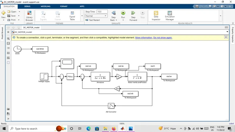
Then,Subsystem Dc motor is connected to the discrete PID controller to maintain the desired speed as it is.
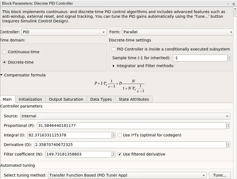
After that Pid controller begin with Kp,Ki,Kd as 1.0,1.0,0 after tuning accordingly, we can adjust Kp,Ki,Kd as
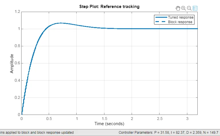
31.58, 82.37, 2.35 respectively. To obtain Control Design Objectives.
Simulink model for the DC motor:
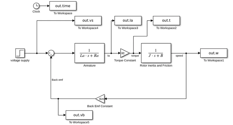
Parameters:
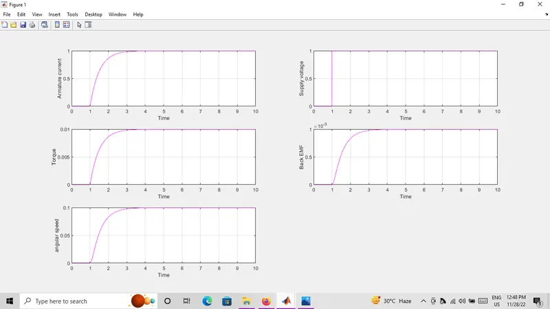
Plotting of Initial Dc Motor Behaviour in Various Scenario Without any Controller:
Design Dc Motor with Discrete PID Contoller:
Here, we make Dc motor as Subsystem and pid Controller is Used to Control Desired Speed.
Block Parameters Of Discrete PID Controller:
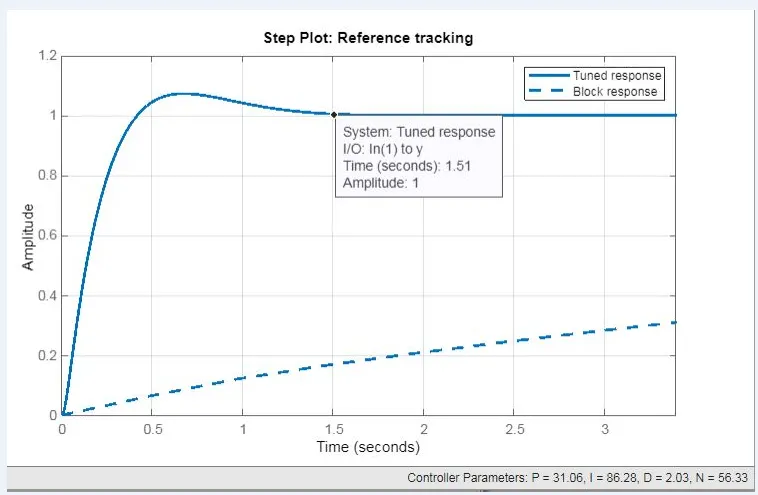
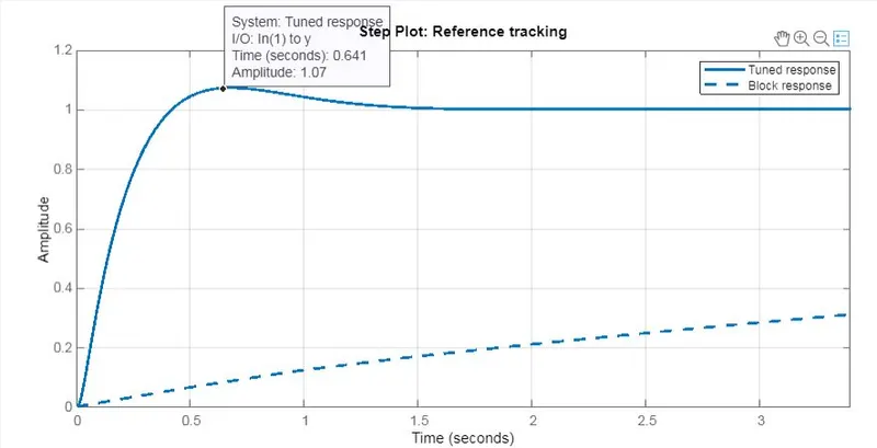
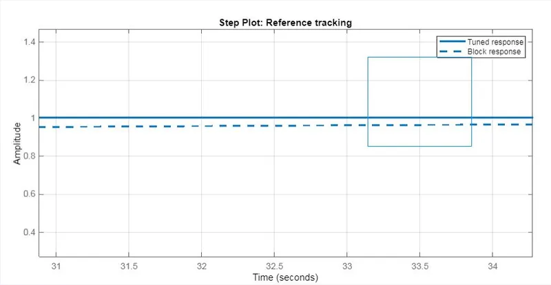
Initially Kp=1,Ki=1,Kd=0, After Tuning we set Kp,Ki,Kd as 31.58, 82.37, 2.35 Respectively. To Obtain Desing Control Objectives Of settling time ,overshoot and Steady State Error within the limit.
Plotting while Tuning as settling time as 1.51 sec:
Plotting while Tuning as overshoot is less than 5%:
Plotting while Tuning as Steady State Error is less than 1%:
Final Plot After Updating into Block:
Maintaining Stability of a dynamic system:
Scope Results:
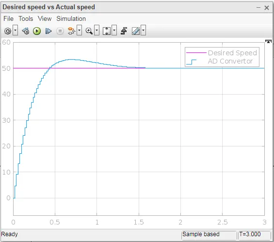
1) To maintain a desired speed for the motor (case 1:Desired Speed = 50):
2) To maintain a desired speed for the motor (case 2:Desired Speed = 230):
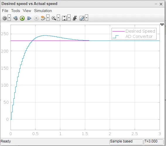
In above two cases,we change desired speed as 50 in case 1 and 230 in case 2 , since the both a case, Plotting Remains same. Hence, we maintain desired Speed For a Dc Motor.
Conclusion:
we have desined In this project a Simulink model for the DC motor as shown in Figure 1.and also we Use the Proportional Integral and Derivative PID control design knowledge gained in the training to design develop and test a controller to maintain a desired speed for the motor
=====================================================================
codes used for plot