Project - Speed Control of a Direct Current (DC) motor
Typically field excitation current (if) is constant for DC motor.
Therefore from the armature circuit in the motor schematic, Applying Kirchoff's voltage law in armature ckt closed loop. we will get,
Vs=Ra*ia+La*dia/dt+vb .....(1)
where vs- supply voltage , ia-armature current, La-armature inductance and vb-back emf
Also back emf ,angular velocity (w or dtheta/dt) and torque (T) are related by,
vb =Kb*dtheta/dt, where Kb is the back emf constant
Therefore rearranging equation (1) ==> La*dia/dt + Ra*ia = Vs - Kb*dtheta/dt .....(2)
T=Kt*ia, where Kt is the torque constant
Also as per Newton's law,
J*d^2theta/dt^2 + B*dtheta/dt = Kt*ia .....(3)
Converting equations (2) & (3) to laplace transform or s-domain,
La*sia(s)+ Ra*ia(s) = Vs(s) - Kb*stheta(s)
Then, ia(s)= [ Vs(s) - Kb*stheta(s) ] / (Ls + R) .....(4)
J*s^2theta(s) + B*stheta = Kt*ia(s)
stheta(s) = w(s) = Kt*ia(s) / (Js + B) .....(5)
substituting value of ia(s) from equation (4) and rearranging the equations for transfer function
w(s) / Vs(s) shown below,
Transfer function (w(s) / Vs(s)) = Kt / [ (Js + B)(Ls + R) + Kt*Kb ]
Based on eqautions (4) and (5) a simulink model for DC motor as per the given motor schematic can be created as shown below,
First let's make a script in matlab for design parameters to model DC motor. Script is shown below,
J = 0.01; %Moment of inertia of rotor in kgm^2
B = 0.1; %Motor viscous friction constant in Nms
Kb = 0.01; %Back emf constant in V/rad/s
Kt = 0.01; %Torque constant in Nm/A
Ra = 1; %Armature resistance in ohm
La = 0.5; %Armature inductance in H
Simulink model for DC motor as per the given motor schematic is shown below,
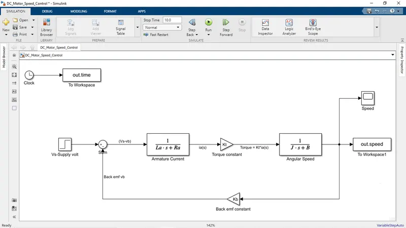
Let's build a PID controller for the above simulink model inorder to acheive the control design objectives such as settling time<2s, Overshoot < 5%, Steady state error < 1%
In general to design PID controller for the DC motor model we need to consider state space equations as shown below,
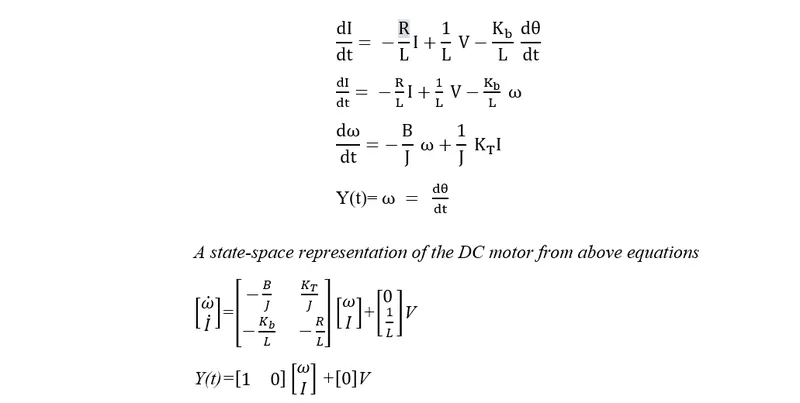
Let's design a PID controller in matlab script for a dynamic system with zeta=0.5,
A = [-B/J Kt/J;-Kb/La -Ra/La]; %state matrix
B = [0;1/La]; %input matrix
fn = 1;
wn = 2*pi*fn;
zeta=0.5;
p1 = -zeta*wn+wn*sqrt(zeta^2-1);
p2 = -zeta*wn-wn*sqrt(zeta^2-1);
P = [p1;p2]; %poles matrix
Let's place the poles using place() and obtain Kp and Kd values which are P and D respectively. Code is written in matlab as shown,
%placement of poles using place function

>> K = place(A,B,P)

K =

   38.3133   -2.8584

>> Kp=K(1)

Kp =

   38.3133

>> Kd=K(2)

Kd =

   -2.8584
Ki is tuning manually to obtain the desied speed response. In other words by tuning Ki we can adjust the speed. The proper set of Kp,Kd and Ki values will help us to get a speed with control objectives met.
PID controller can be expressed mathematically with error signal e(t) as shown below,

Let's implement this PID contoller in DC motor simulink model as shown below,
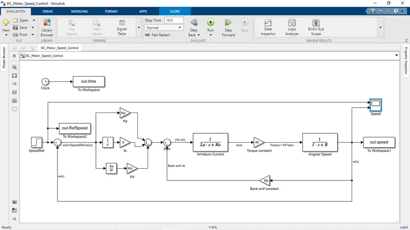
Input ref speed is set to 20 and intially Ki is set to zero. Model has run and let's check the plots obtained from scope is shown below,
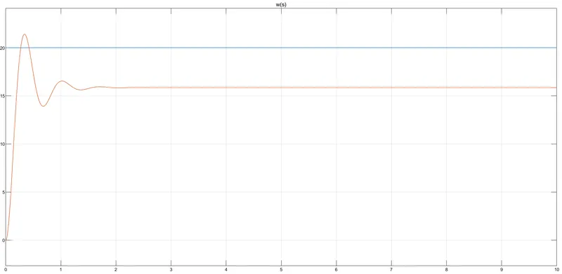
As u can see settling time<2s, Overshoot < 5%, Steady state error < 1% are not met. Let's tune Ki and obtain desired response, Ki=50 and see the response,
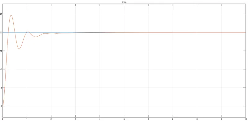
Let's adjust Kp and Kd for to make overshoot and settling time within limit. Let's set Kp=2,5;
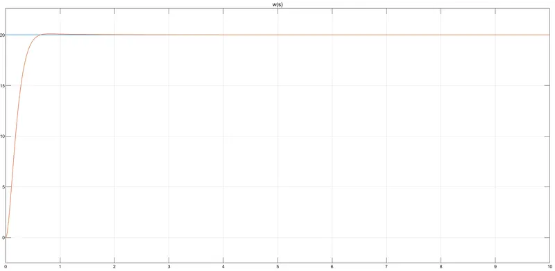
From the above response it is clear that we got a stable steady state response as per the reference input with control objectives are met.