Project - Speed Control of a Direct Current (DC) motor
Project - Speed control of Direct Current (DC) Motor Using PID controller.
Aim -
In this project, a Simulink model for the DC motor will be first developed per the schematic shown in Figure 1.
Use the Proportional, Integral, and Derivative (PID) control design knowledge gained in the training to design, develop and test a controller to maintain a desired speed for the motor.
Answer - First of all we see and aknowledge more about Dc motor and PID controller to get the proper knowledge for creating the model.
1) Mathematical modeling - we create the expression for our model from kirchoff closed loop law and newtons law . After combining both we transform it using laplace transform . Now we get a transfer function to set it into our DC motor model for putting the values and get desired values. we set some parameters as you can see below.
J = 0.01; % moment of inertia of the rotor in kg-m^2
B = 0.1; % motor viscous friction constant in N-m-s
Km = 0.01; % Back emf const in V/rad/sec
Kt = 0.01; % motor torque const in N-m/amp
Ra = 1.0; % resistance of armature circuit in ohm
La = 0.5; % inductance of armature circuit in Henry
fn = 1.0; % natural frequency
wn = 2*pi*fn;
zeta = 0.5; % damping coefficient
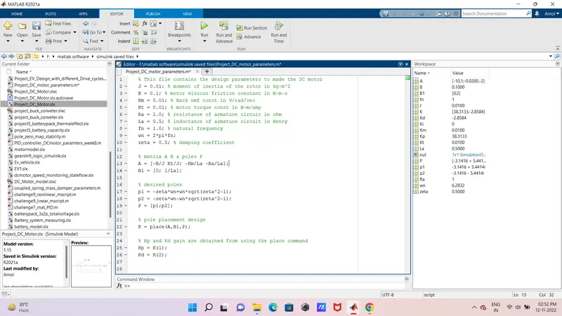
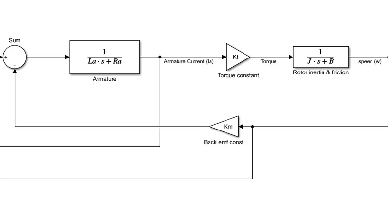
2) Modeling an Electrical Engineering system - Simulink based modeling -
we create DC motor model with some simulink blocks for our mscript or parameters to get the values in it. After all that we set also there transfer function to get the desired output.
3) control design for PID controller - Again we get the values for our PID contoller by pole placing method using in matlab mscript file. we get Kp and Kd value , for the ki we set it for a certain value to get the sired ouput for our controller.
% matrix A B & poles P
A = [-B/J Kt/J; -Km/La -Ra/La];
B1 = [0; 1/La];
% desired poles
p1 = -zeta*wn+wn*sqrt(zeta^2-1);
p2 = -zeta*wn-wn*sqrt(zeta^2-1);
P = [p1;p2];
% pole placement design
K = place(A,B1,P);
% Kp and Kd gain are obtained from using the place command
Kp = K(1);
Kd = K(2);
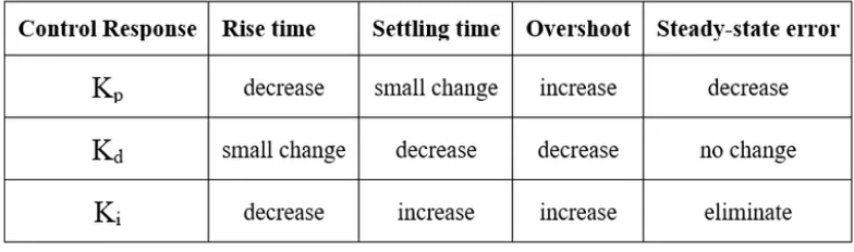
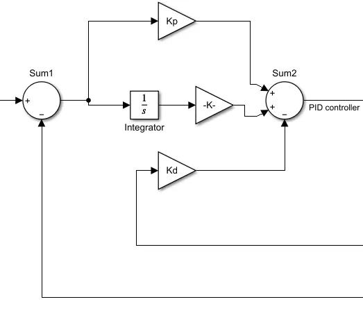
4) Control design with DC motor design modeling -
As we know by above steps we create a PID controller for our DC motor to get the steady state or stable state for our system or model .we create that and simulate for 10 sec. with modeling setting we set the solver to fixed step and ode4 method to get desired response.
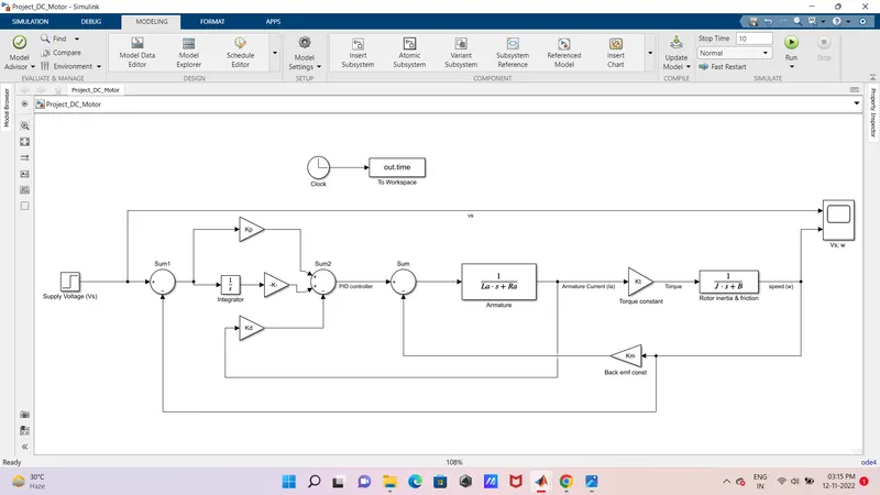
5) Result - stability of system - First of all we simulate our model for 0 ki ratio but we got some wrong response from that , we ran it for particular time to get the desired response , we set the Ki value to the 34.567 and finally we get the stable state for our system and we set it too. By changing the step time to the 5 and initial value with 5 and final value with 10 we get the result as shown below for our model.
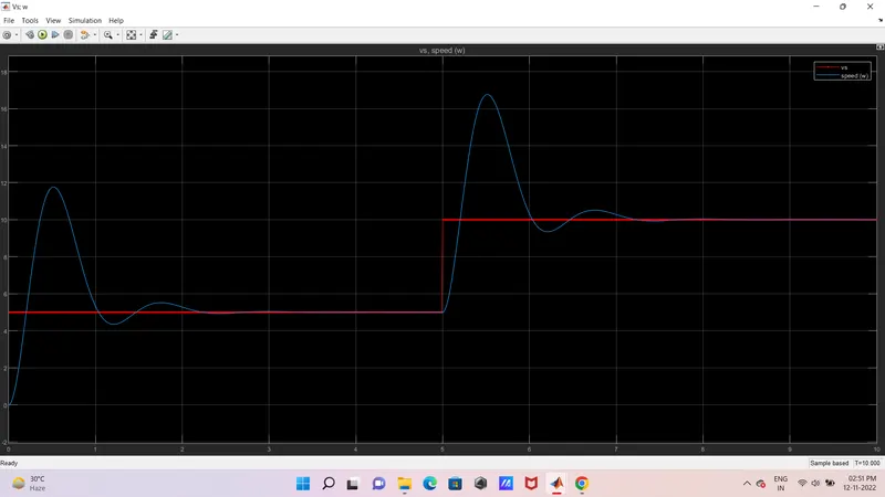
* conclusion - we conclude that after designing the model we have to set the values properly for our system like zeta and KI values because the stable state belongs with that if any of the value change the system to be overshoot or undershoot . But the correct number of expressed value we get steady state with stable system to get deired output with no error.
Thanking you.