Project - Speed Control of a Direct Current (DC) motor
Use the Proportional, Integral, and Derivative (PID) control design knowledge gained in the training to design, develop and test a controller to maintain a desired speed for the motor.
Selecting the parameters for designing the DC Motor .
% This file contains design parameters for DC motor
J = 0.01; % Moment of inertia of rotor in kg-m^2
B_fric = 0.1; % Motor viscous friction constant in N-m-s
Kt = 0.01; % Motor torque constant in N-m/amp
Km = 0.01; % Back emf constant in v/rad/s
Ra = 1.0; % Resistance of armature circuit
La = 0.5; % Inductance of armature circuit
%Design of PID Controller
A = [-B_fric/J Kt/J; -Km/La -Ra/La];
B = [0 ; 1/La];
% Placement of Poles
fn = 1.0;
wn = 2*pi*fn;
zeta = 0.98; %selecting this value of zeta for getting stable system.
p1 = -zeta*wn + wn*sqrt(zeta^2-1);
p2 = -zeta*wn - wn*sqrt(zeta^2-1);
P = [p1;p2]; % poles of the system
K = place(A,B,P);
Kp = K(1); % proportionality constant
Kd = K(2); % derivative constant
Ki = 0; % integral constant
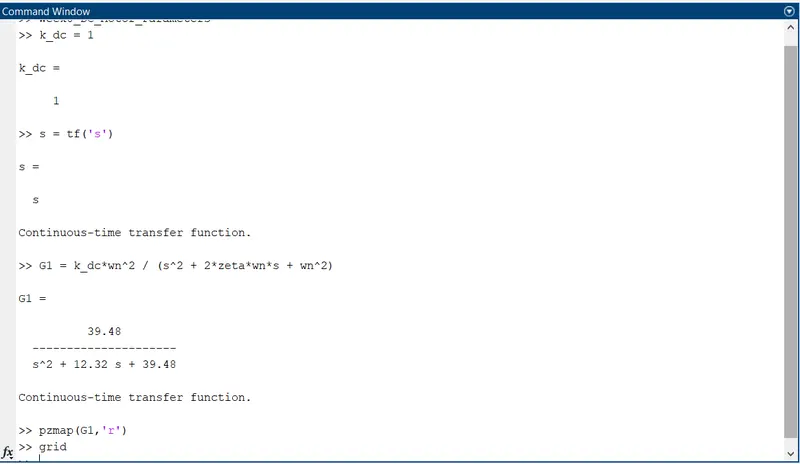
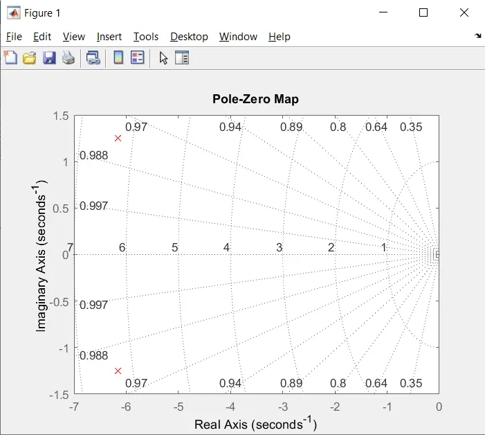
Verify the stability of the system by checking the location of poles of the system :
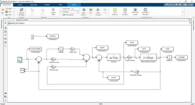
Simulink Model :
Ref_speed = 40
Kp = 8.15
Kd = 0.1575
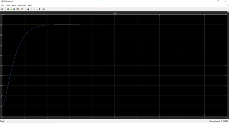
Output :
Case 1: Ki = 0
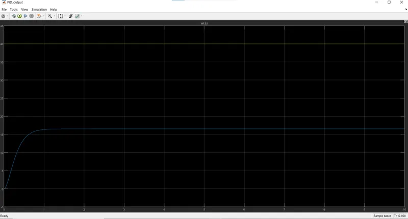
Case 2: Ki = 50
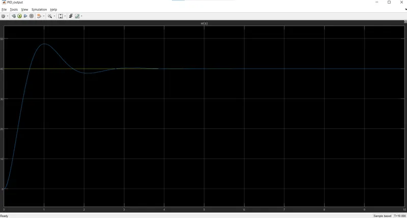
When we keep on increasing the value of Ki from 50 to 100, we observe oscillations in the output which means the system is not getting stable for suh high values of Ki.
For Ki = 100;
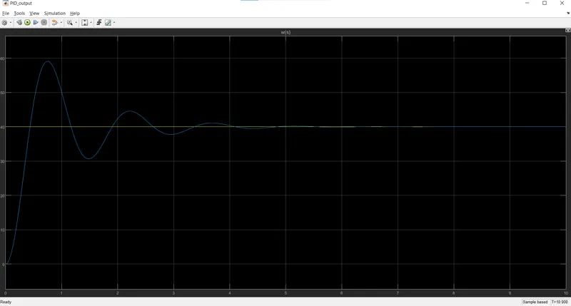
So we decease the value of Ki until we observe the stable output matching with the ref_speed track.
Case 3: Ki = 25
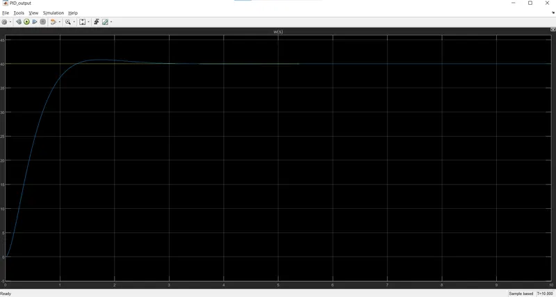
Case 4: Ki = 20
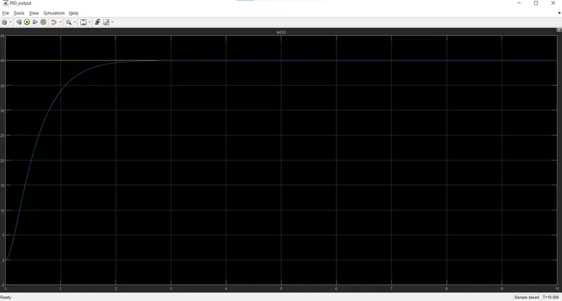
Case 5: Ki = 21 ( most stable output )
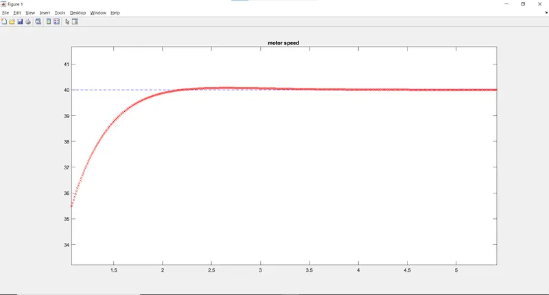
plot(out.time,out.ref_speed,'b--'); grid; hold on;
plot(out.time,out.w,'rx'); grid; title('motor speed ');
Conclusion :
For zeta = 0.98, Kp = 8.15 Kd = 0.1575, Ki = 21 PID controller works best and the system is stable