Project - Speed Control of a Direct Current (DC) motor
Project dc motor
J = 0.01; % Moment of inertia of the rotor in kg-m^2
b = 0.1; % Motor viscous friction constant in N-m-s
Km = 0.01; % Back EMF constant in v/rad/s
Kt = 0.01; % Motor torque constant in N-m/amp
Ra = 1.0; % Resistance of the armature circuit in ohms
La = 1.0; % Inductance of the armature circuit in henries
% Equivalnt wn
%sqrt (k/m)
fn = 1.0;
wn = 2*pi*fn;
% design Parameter
zeta = 0.98; % underdamped
%%
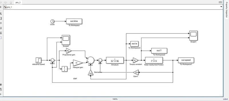
%% initial value = 0
% Kp and Kd are gains are obtained from an earlier design
Kp = K(1);
Kd = K(2);
Ki = 0;
% manual put value of kp,kd
Kp = 0.0
Kd = 0.0
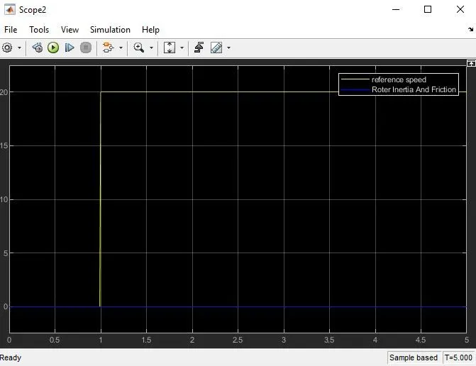
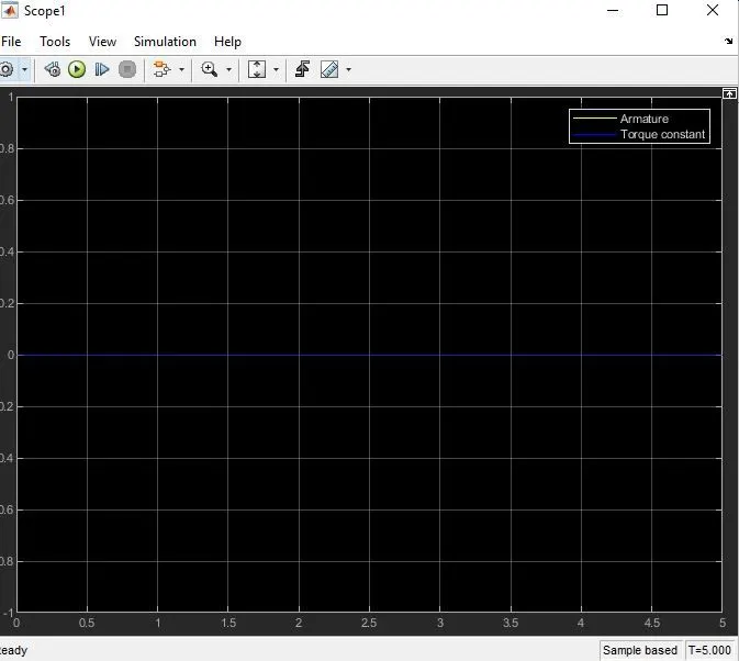
%% initial value = 1
% Kp and Kd are gains are obtained from an earlier design
Kp = K(1);
Kd = K(2);
Ki = 82.37;
% manual put value of kp,kd
Kp = 55.0
Kd = 4.85
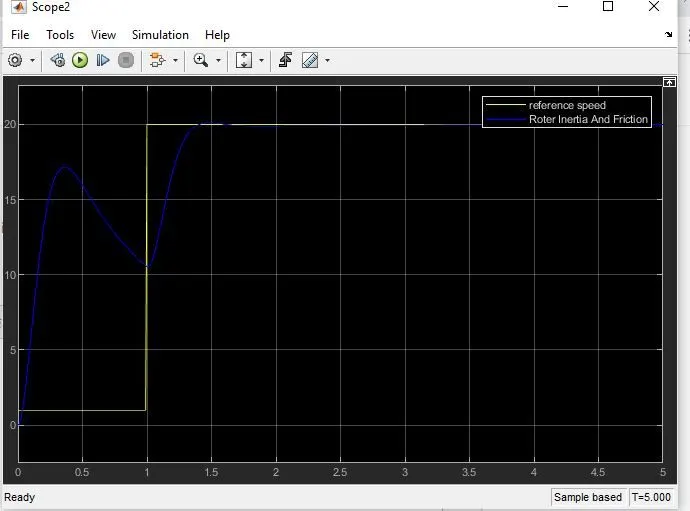
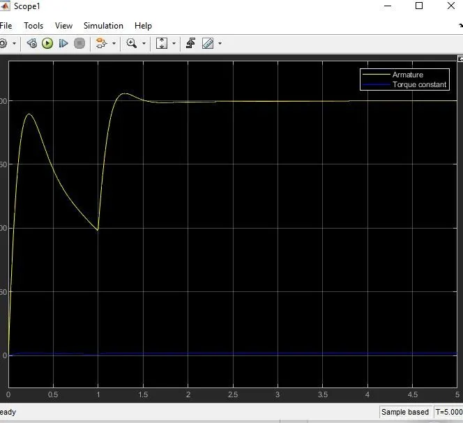
M file
J = 0.01; % Moment of inertia of the rotor in kg-m^2
b = 0.1; % Motor viscous friction constant in N-m-s
Km = 0.01; % Back EMF constant in v/rad/s
Kt = 0.01; % Motor torque constant in N-m/amp
Ra = 1.0; % Resistance of the armature circuit in ohms
La = 1.0; % Inductance of the armature circuit in henries
% Equivalnt wn
%sqrt (k/m)
fn = 1.0;
wn = 2*pi*fn;
% design Parameter
zeta = 0.98; % underdamped
% desired poles
p1 = -zeta*wn+wn*sqrt(zeta^2-1);
p2 = -zeta*wn-wn*sqrt(zeta^2-1);
P = [p1;p2];
% A and B Matrix
A = [-b/J Kt/J;-Km/La -Ra/La];
B = [0;1/La];
% poles placement design
K = place(A,B,P);
% Kp and Kd are gains are obtained from an earlier design
Kp = K(1);
Kd = K(2);
Ki = 82.37;
% manual put value of kp,kd
Kp = 55.0
Kd = 4.85