Project - Speed Control of a Direct Current (DC) motor
Script Code
clc;
clear all;
% This file contains parameters for DC motor design
J= 0.01; %Inertia
B= 0.1; %friction
Km= 0.01; %back emf
Kt= 0.01; %torque
Ra= 1; %resistance
La= 0.5; %inductance
%% Design of PID Controller
A=[-B/J Kt/J; -Km/La -Ra/La];
B=[0; 1/La];

%% Placement of Poles
fn= 1;
wn= 2*pi*fn;
z= 0.5;
P1= -z*wn+wn*sqrt(z^2-1);
P2= -z*wn-wn*sqrt(z^2-1);
P= [P1; P2]
K= place(A,B,P)

k_dc= 1; %the DC gain of the system is 1
s= tf('s');
G1= k_dc*wn^2/(s^2+2*z*wn*s+wn^2);
pzmap(G1,'r')
Output
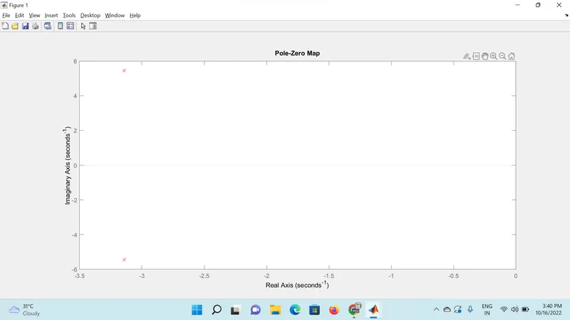
P =

  -3.1416 + 5.4414i
  -3.1416 - 5.4414i


K =

   38.3133   -2.8584

>> 
Summary
Poles are located on -2 and -3 which lie on the left-hand plane which indicates the system is stable.
Case-1
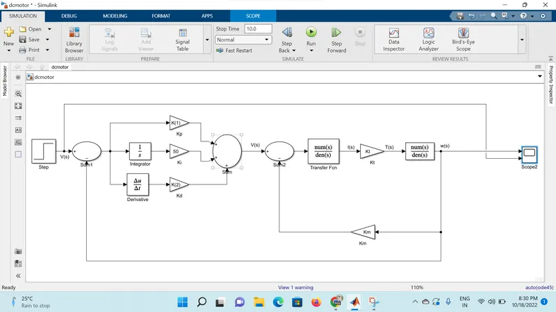
Output Scope
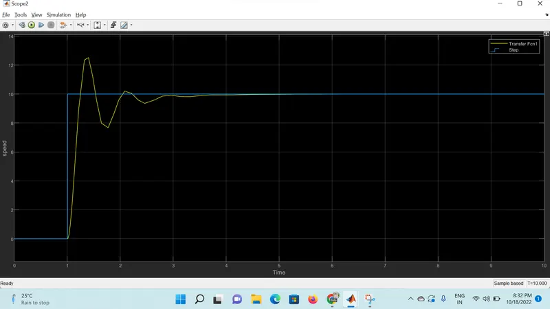
Summary
When Ki taken as 50 and step speed is taken as 10.
At 1.4 sec system gone to overshoot condition with 12.2 rpm of speed and 1.8 sec system gone to undershoot condition with 7.9 rpm of speed the reference signal simulates the actual signal at 4.5 sec and meet the Steady state condition.
Case-2
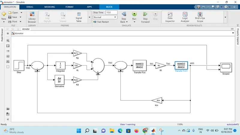
Output Scope
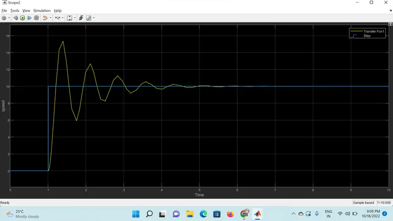
Summary
When Ki taken as 150 and step speed is taken as 10.
At 1.4 sec system gone to overshoot condition with 15.2 rpm of speed and at 1.8 sec system gone to undershoot condition with 6 rpm of speed again the system went for overshoot condition at 2.2 sec for 12.2 rpm and went for unndershoot condition at 2.5 sec for 8.1 rpm of speed, the reference signal simulates the actual signal at 5.8 sec and meet the Steady state condition.