Project - Speed Control of a Direct Current (DC) motor
PROJECT - Speed Control of a Direct Current (DC) motor
Aim: To develop a Simulink model for the DC motor as per the schematic given and use the Proportional, Integral, and Derivative (PID) control design knowledge gained in the training to design, develop and test a controller to maintain a desired speed for the motor.
Results
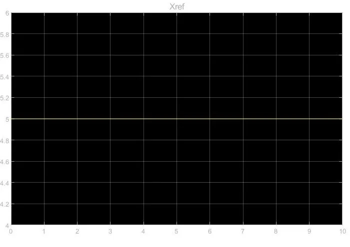
The above figure shows the plot of input step signal with magnitude 5.0
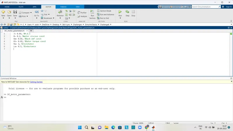
The above figure shows the function created in Matlab for giving the input parameters. Here the assumed input values are:
J= 0.01 kg-m^2
B= 0.1 N-m-s
Km= 0.01 v/rad/s
Kt= 0.01 N-m/amp
Ra= 1 ohms
La= 0.5 henry
Kp= 3.8602
Kd=628.32
Ki= 8000
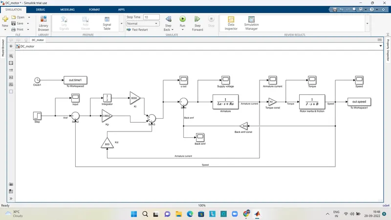
#The above figure shows the Simulink model to design a PID controller for the DC Motor.
# Here for the input step signal, step block is used with magnitude 5.0 and for the arithmetic calculations, Sum and Gain blocks are used. The input values of the gain block is the values of Km, Kt, Kp, Kd and Ki, which is obtained by calculations in Matlab.
# Then the PID controller model is connected with the DC motor model to form the complete desired model. The speed is fed back to the reference signal and armature current to the Kd block.
# At last, the output results are plotted using scope block, to obtain the graph of speed, torque and armature current of DC motor.
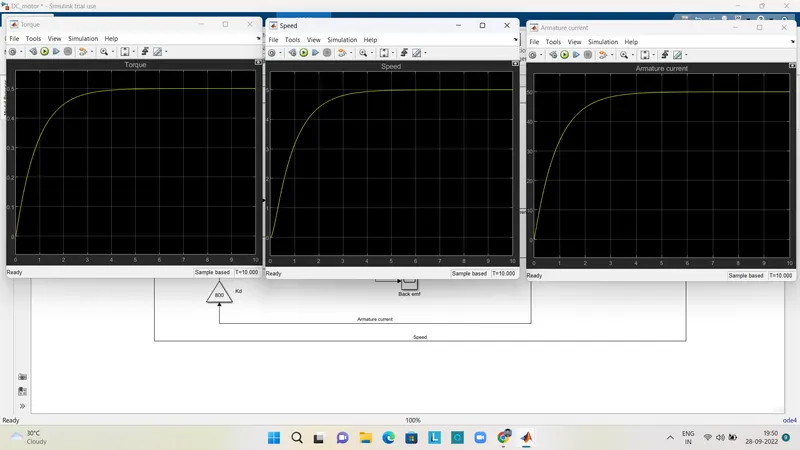
The above figure shows the plot of the speed, torque and armature current values of a PID controlled DC motor, for a step signal with magnitude 5.0