Project - Position control of mass spring damper system
Aim :
To design the project of position control of mass spring damper system using matlab simulink model of transfer function of a mass
spring damper system and use it in the model. Add a PID controller to adjust the force on mass so that its position follows a
reference signal.
OBJECTIVE :
transfer function of a mass spring damper system and use it in the model. Add a PID controller to adjust the force on mass so
that its position follows a reference signal. the matlab model of the pid control and transfer function pulse wavefrome generator.
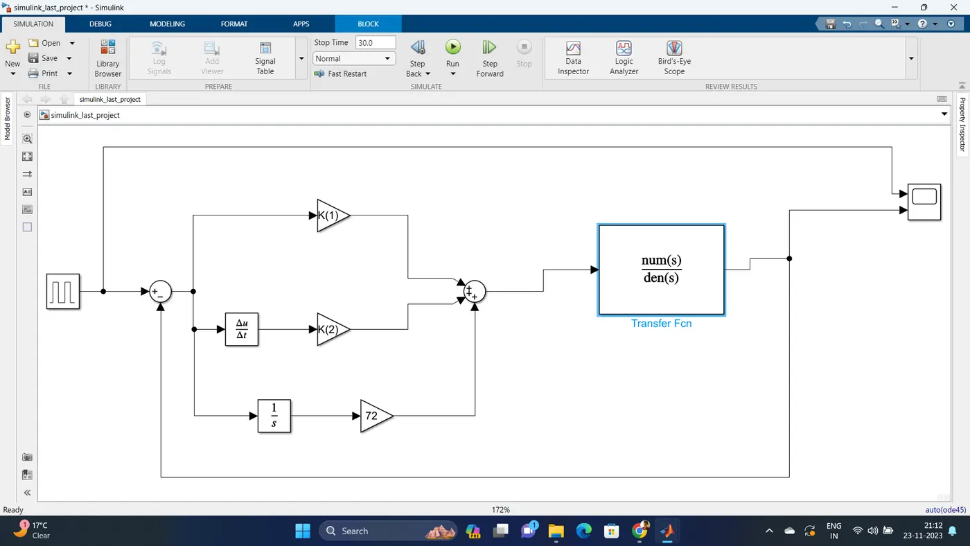
This example shows a controlled mass-spring-damper. A controller adjusts the force on the mass to have its position track a
commandsignal. The initial velocity for the mass is 10 meters per second. The controller adjusts the force applied by the Force
Source to track the stepchanges to the input signal.
TRANSFER FUNCTION :
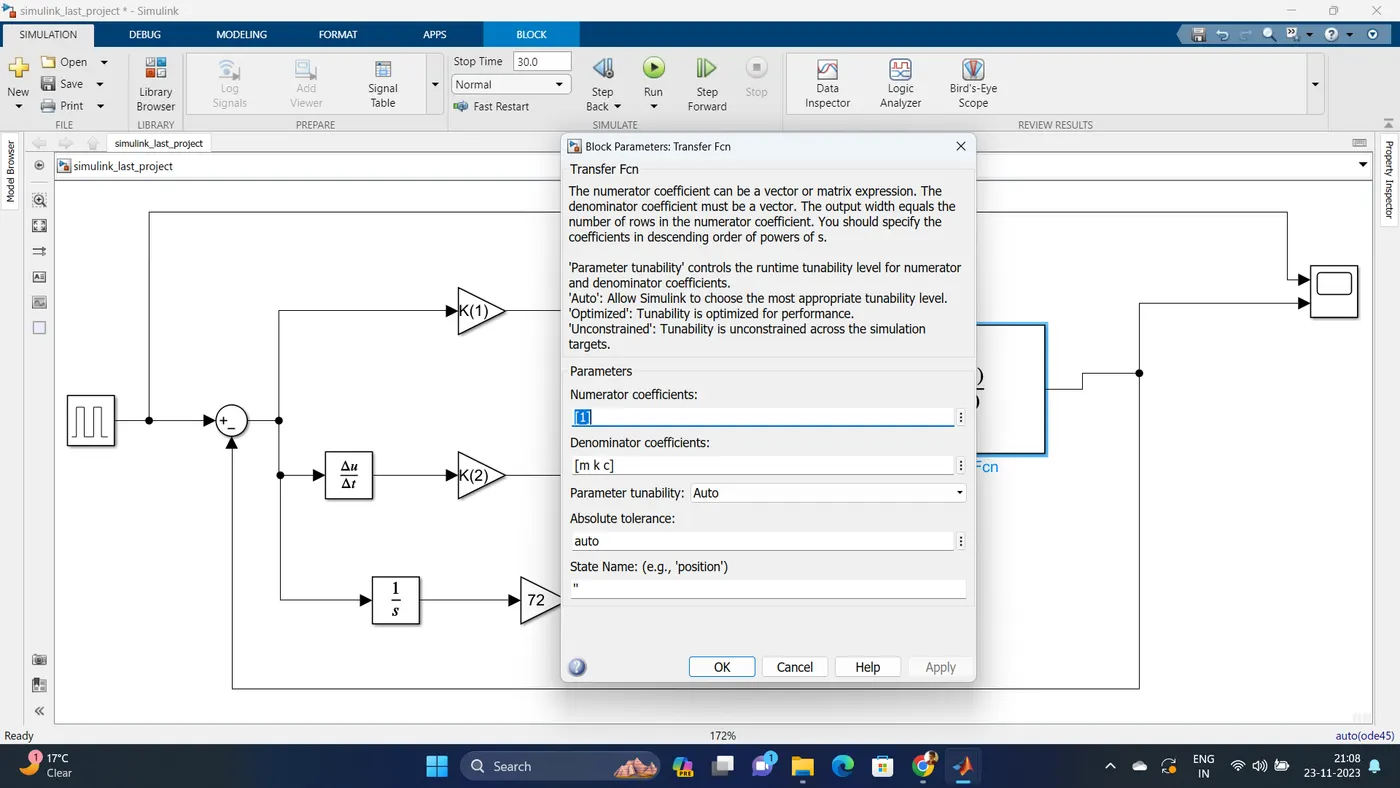
The numerator coefficient can be a vector or matrix expression. The denominator coefficient must be a vector. The output width equals
the number of rows in the numerator coefficient. You should specify the coefficients in descending order of powers of s.
'Parameter tunability' controls the runtime tunability level for numerator and denominator coefficients. 'Auto': Allow Simulink to choose
the most appropriate tunability level. 'Optimized': Tunability is optimized for performance. 'Unconstrained': Tunability is unconstrained
across the simulation targets.
Code :
clc;
close all;

% initial conditions Position control of mass spring damper system
m = 3.6; % kg
k = 400; % N/m
c = 100; % Ns/m

% Pole placement design
fn=(1/(2*pi))* sqrt (k/m); % 1Hz neutral frequency design
wn = 2*pi*fn; % Neutral frequency in rad/s

% A & B matrix value
A = [0 1; -k/m -c/m]; % A is using matrix of c ans k dived value of mass
B = [0; 1/m]; % B is the 1 ovear mass value

% Design values
zeta = 0.9; % for an under-damped behavior

% Desied poles value
p1 = -zeta*wn+wn*sqrt(zeta^2-1);
p2 = -zeta*wn-wn*sqrt(zeta^2-1);
p= [p1;p2];

% place comment is the Kp and Kd value
K = place(A,B,p); % Kp = K(1), Kd = K1(2)
%End
To design a closed loop control scheme for a DC motor the following changes need to be done in the model in the previously created model.
- Speed is the controllable parameter, so we will set the reference speed in step block as 10,20, 40 whichever you want.
- Subtract the actual speed from the reference speed to generate the error signal e(t)
- Add Kp as K(1) and Kd as K(2) parameter determined from place command (K=place(A,B,P)). (use gain block to mention values of Kp, Kd,
- and Ki)
- The feedback for Kd is provided from the output current of the plant/model (figure 1). OR we can take feedback (error speed signal as input
- to Kd shown by figure 2)
- Add Ki manually with gain and integrator block and tune different values of Ki and check the impact of it on results.
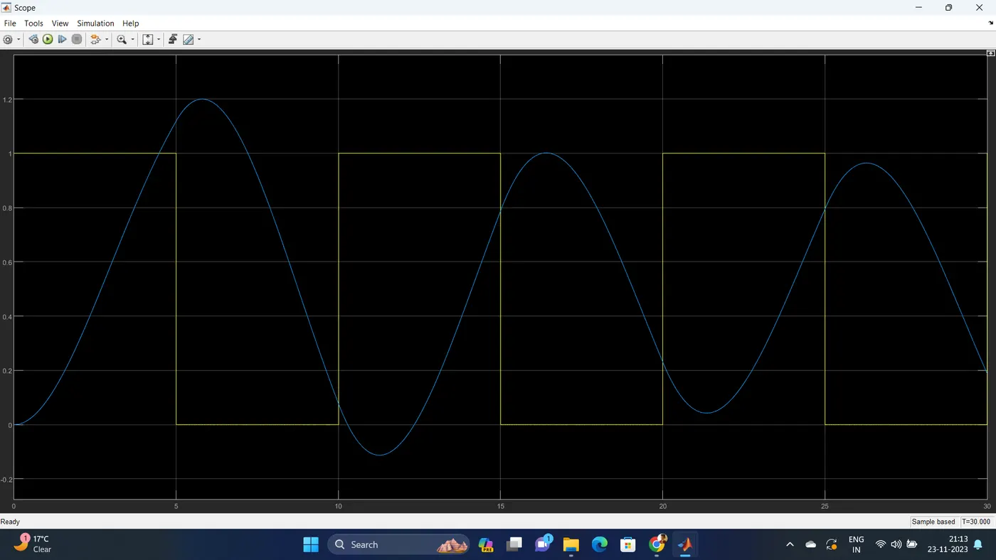
Scope output :