Project - Position control of mass spring damper system
SIMULINK Final Project -
AIM - To obtain the transfer function of a spring mass damper system and use it in model. Design a PID controller to adjust the force on mass such that its position follows a reference signal.
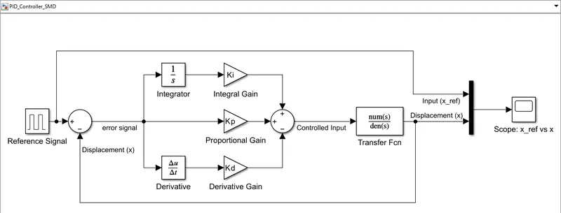
Objective - To design a spring mass damper system using transfer function block in Simulink with the given parameters. Design PID controller for the same to control the input force such that the position of the mass follows the input reference signal.
Design Parameters for Spring Mass Damper System -
Mass (m) = 3.6 Kg
Spring Constant (k) = 400 N/m
Damping co-efficient (c) = 100 Ns/m
Position reference signal -
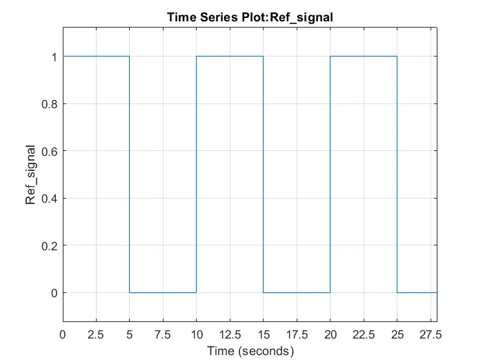
Design Process of Simulink Model -
The transfer function for spring mass damper system is given as -
X(s) / F(s) = 1 / (m*s^2 + c*s + k)
All the given data and required calculation are done in Matlam (.m) file which will load the workspace for the required variable for Simulink Model.
Matlab (.m) file for given data & controller gain (Kp, Kd, Ki) calculations is defined as -
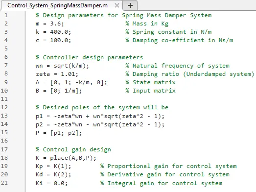
Simulink Model for the Spring Mass Damper system using Transfer function block is as below -
The initial values of control gains are calculated as -
Kp = 3.5811e-13
Kd = 76.6536
Ki = 0.0
Scope output for the input reference signal versus the displacement on initial gains (Kp, Kd, Ki) value is as below -
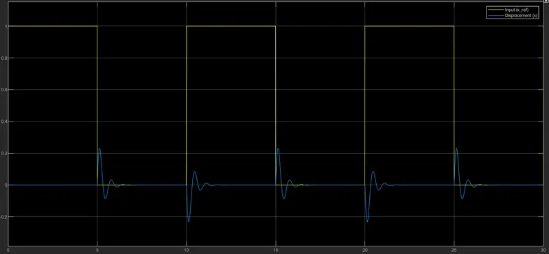
It is evident from the scope output that our displacement (x) does not follow the input (x_ref) signal, that means our controller is not effective.
Thus to improve the control system efficiency we will alter the values of Kp, Kd & Ki gains to achieve the desired output.
The impact of changing the gain values can be described as -
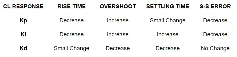
So, by altering the gain values & monitoring the output we get the output in desired range at the final gain values of
Kp = 5000,
Kd = -150,
Ki = 7500,
The scope output with the updated gain values is as below -
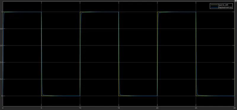
From the updated scope output it can be seen that the displacement (x) is well keep in track with our input reference signal (x_ref) that means our control system is effective & meets the design requirement.
CONCLUSION -
Using the PID Control System design we can effectively control the applied external force on the plant system to get the desired output.
The effectivity of the control system can be improved by fine tuning the values of controller gains (Kp, Kd, Ki). Thus increasing the results & performance of the control system.
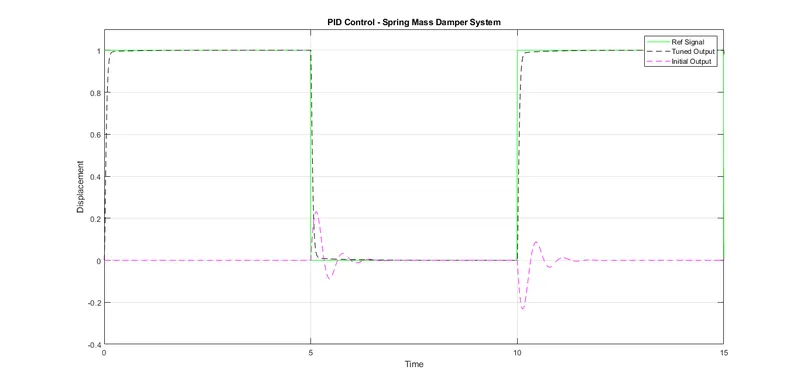
Graph for Ref Signal vs Output with Initial Gain vs Output with Tuned Gain values.
# All files attached for better understanding.