%DC motor Parameters
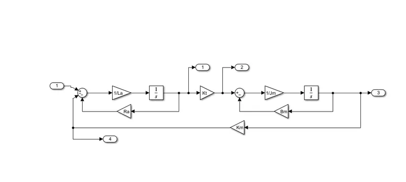
Jm = 0.01; %Moment of Inertia of Rotor (Kgm^2)
Bm = 0.1; %Motor viscous friction constant (Nms)
Km = 0.01; %Back EMF constant (V/rad/s)
Kt = 0.01; %Motor Torque constant (Nm/Ampere)
Ra = 1; %Armature Resistance (ohm)
La = 0.5; %Armature Inductance (H)

%PID design from DC_motor_PID_design.m
%Load the parameters of DC motor

%PD design
A = [-Bm/Jm Kt/Jm; -Km/La -Ra/La];
B = [0; 1/La];
%pole placement design
f = 1;
wn = 2*pi*f;
zeta = 0.5;
p1 = -zeta*wn + wn*sqrt(zeta^2-1);
p2 = -zeta*wn - wn*sqrt(zeta^2-1);
P = [p1;p2];
K = place(A,B,P);
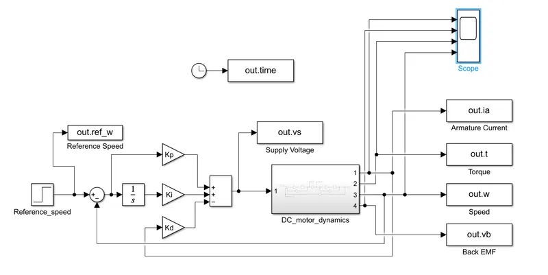
Kp = K(1);
Kd = K(2);
Kp = 20;
Kd = -0.9;
Ki = 3;

%Plotting the graphs from dc_motor_plot.m
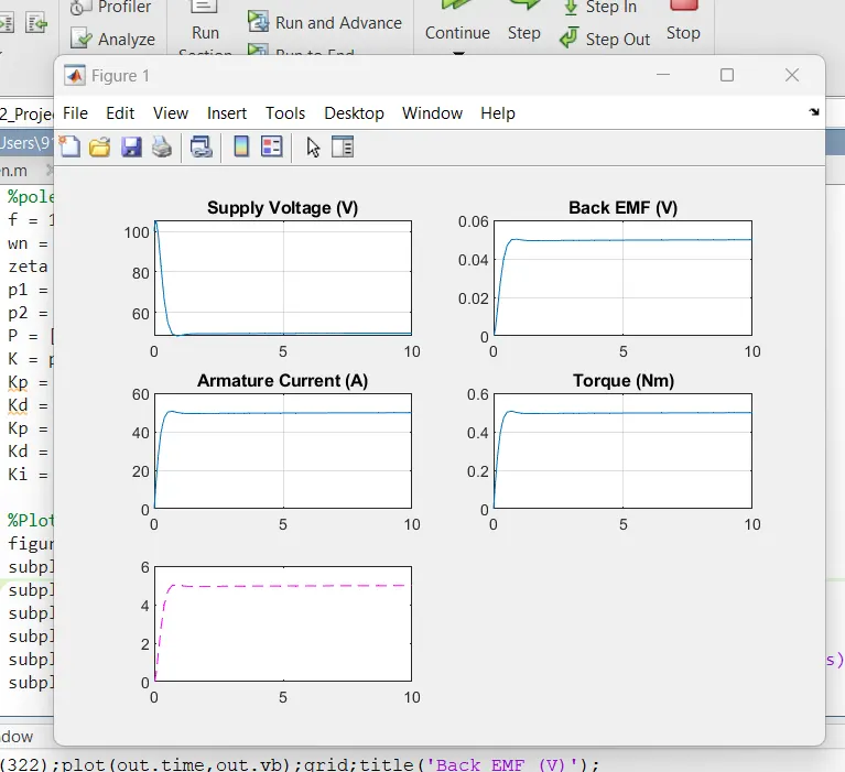
figure(1)
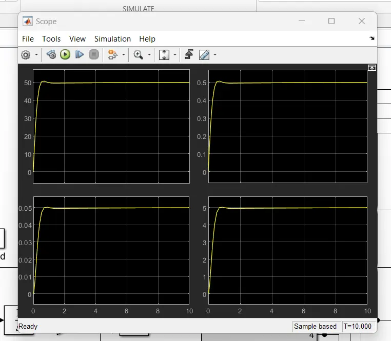
subplot(321);plot(out.time,out.vs);grid;title('Supply Voltage (V)');
subplot(322);plot(out.time,out.vb);grid;title('Back EMF (V)');
subplot(323);plot(out.time,out.ia);grid;title('Armature Current (A)');
subplot(324);plot(out.time,out.t);grid;title('Torque (Nm)');
subplot(325);plot(out.time,out.ref_w,'b--');grid;hold;title('Refernce Speed (rad/s)');
subplot(325);plot(out.time,out.w,'m--');