Project - Position control of mass spring damper system
Obtain the transfer function of a mass spring damper system and use it in the model. Add a PID controller to adjust the force on mass so that its position follows a reference signal.
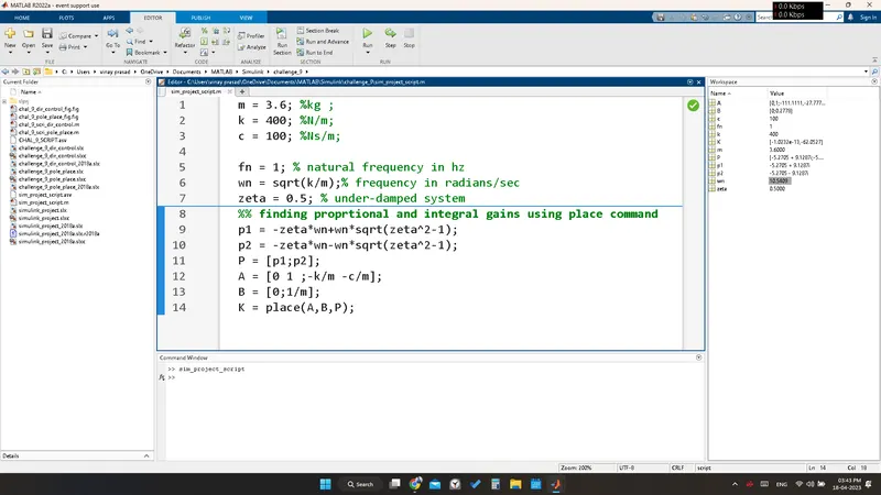
The Matlab script is written as follows
- The given values of m,c, and k are written in the script .
- zeta is set to 0.5 and wn = sqrt(k/m).
- The matrices A and B are derived as A = [0 1;-k/m -c/m] and B = [0;1/m].
- place command is used to obtain the control gains (kp and kd).
- then the script is run.
m = 3.6; %kg ; mass
k = 400; %N/m; spring constant
c = 100; %Ns/m; damping coefficient
fn = 1; % natural frequency in hz
wn = sqrt(k/m);% frequency in radians/sec
zeta = 0.5; % under-damped system
%% finding proportional and integral gains using place command
p1 = -zeta*wn+wn*sqrt(zeta^2-1);
p2 = -zeta*wn-wn*sqrt(zeta^2-1);
P = [p1;p2];
A = [0 1 ;-k/m -c/m];
B = [0;1/m];
K = place(A,B,P);
The model is created using transfer function, sum, gain, integrator, scope, and pulse generator Blocks.
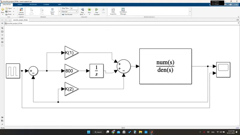
- The pulse generator block is added to the workspace and its parameters are modified so that the desired reference signal mentioned in the question is obtained.
- The transfer function of the spring-mass damper is obtained as [G(s) = 1/ms^2+cs+k].
- The transfer function block is added to the workspace and the denominator coefficients are modified to be [m c k].
- The numerator coefficient is left as '1'.
- then the PID controller is designed such that the position of mass follows a reference signal.
- The main goal is to decrease the rise time to as minimal as possible.
- And to get an acceptable overshoot and undershoot and eliminate steady-state error completely.
- After connecting the gains to the sum(++-) block , the sum block is connected to the transfer function block.
- The transfer function block is connected to the scope.
- The model is run for 28 sec and the results from the scope are observed.
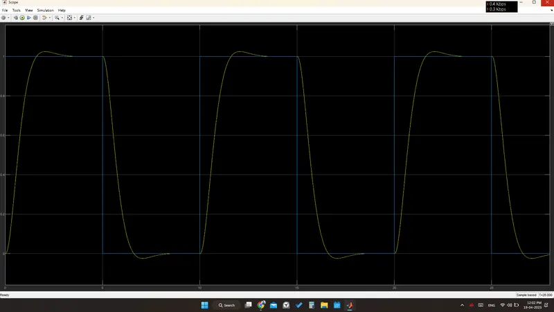
IN THE FIRST CASE KI IS SET TO 500 AND THE OUTPUT FROM THE SCOPE IS AS FOLLOWS:
- The Rise time is more in the following figure.
- Acceptable overshoot and undershoot cannot be seen.
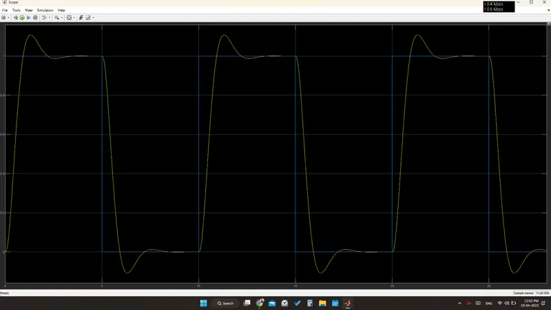
IN THE SECOND CASE KI IS SET TO 800 AND THE OUTPUT FROM THE SCOPE IS AS FOLLOWS:
- The Rise time was less when compared to the previous figure is more.
- Acceptable overshoot and undershoot can be seen.
Conclusion:
- The results from the PID controller gave good results with KI set to 800 as the rise time is decreased.
- so, we can see that the position of the mass is following the reference signal.
THANKING YOU SIR/MAM
N.VINAY PRASAD