Project - Position control of mass spring damper system
1.
A transfer function of a mass spring damper system with PID controller to adjust the force on mass so that its position follows a reference signal.
Take m = 3.6 kg
k = 400 N/m
c = 100Ns/m
simulink model is created using sum, pulse generator, gain, integrator, scope , derivative, clock, workspace blocks.
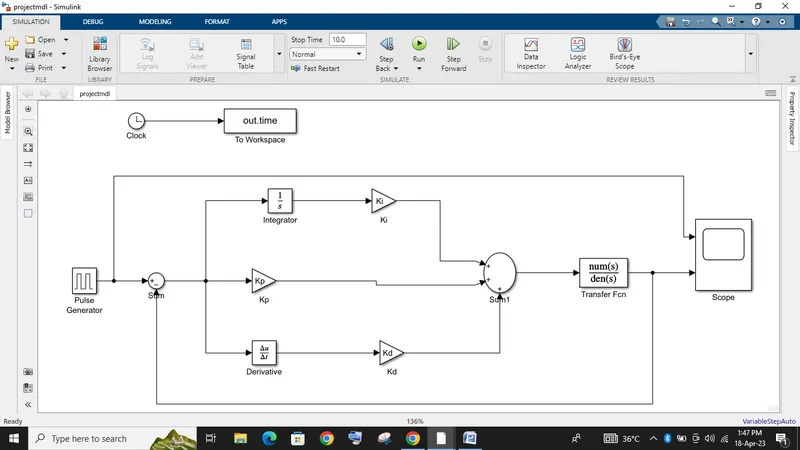
model settings are given as start time 0, stop time 20 sec, solver as odea 4 ( Runge-Kutta ) & variable type with step time as 0.01
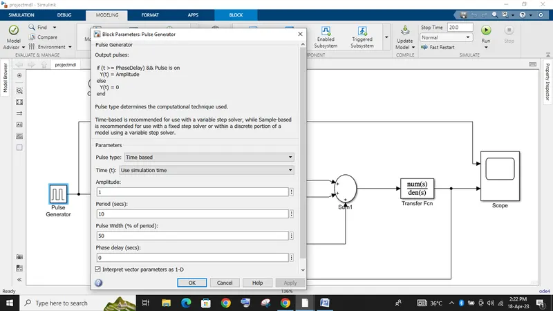
pulse generator is used and these values are given
amplitude = 1
period = 5
pulse width = 50%
these values are derived from the refernce signal provided in question
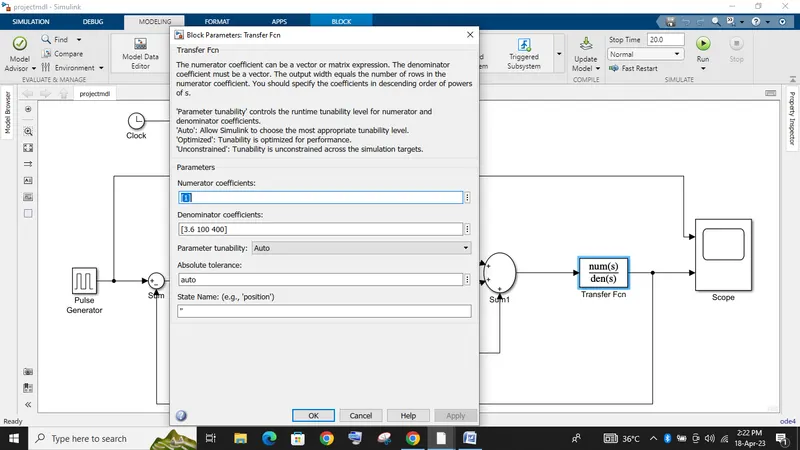
the transfer function for a spring mass damper system is 1 / ( m * s^2 + c * s + k )
where the value of mass (m) , damping coefficient (c) , spring constant (k)
m = 3.6 kg
k = 400 N/m
c = 100 Ns/m
these values of m , c , k are given in the denominator as the differential order ( high to low )
where numerator will be 1
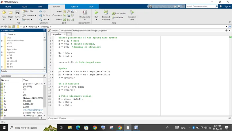
Wn = k/m
Wn / (2*pi) = fn = 1
Underdamped case
zeta = 0.99
poles
p1 = -zeta * Wn + Wn * sqrt(zeta^2-1);
p2 = -zeta * Wn - Wn * sqrt(zeta^2-1);
P = [p1;p2];
A & B matrices
A = [0 1;-k/m c/m];
B = [0;1/m];
Poles placement design
K = place (A,B,P);
K1 = Kp = K(1)
K2 = Kd = K(2)
except for the value of Integral Gain ( Ki ) all other values remain same.
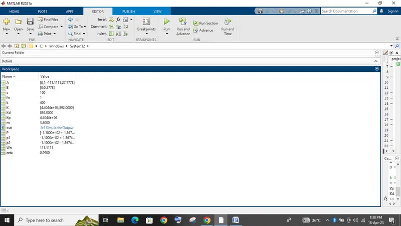
when Integral gain
Ki = 0
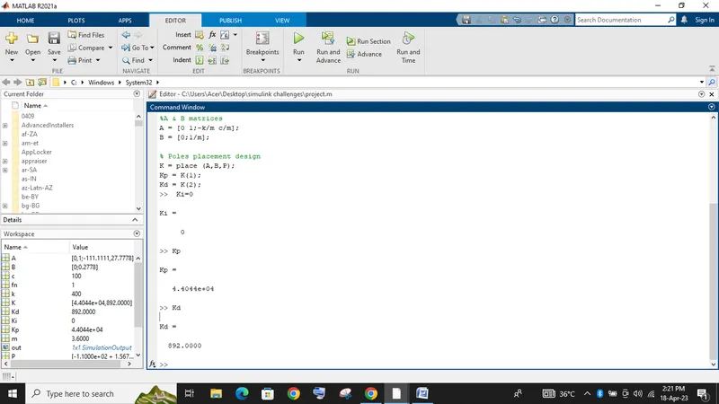
when Ki = 0
we can observe that there is a steady state error between the reference and simulated signal.
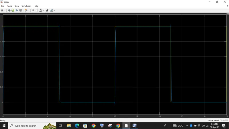
Ki = 5000
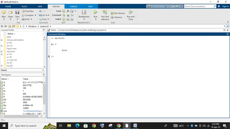
when Ki = 5000
we can verify that the steady state error is low when compared to Ki = 0
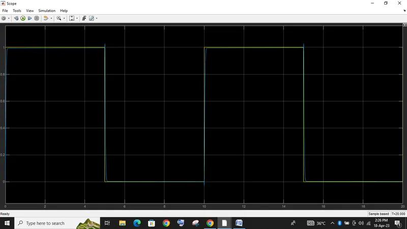
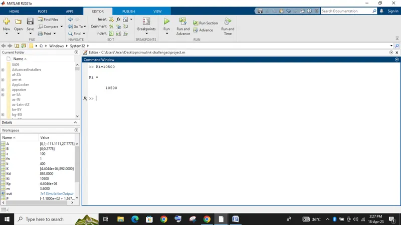
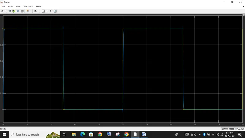
Ki = 10500
as the Integral Gain ( Ki ) increases the steady state error decreases
conclusion:
The transfer function of a mass spring damper system and use it in the model. Add a PID controller to adjust the force on mass so that its position follows a reference signal.
Take m = 3.6; %kg k = 400; %N/m c = 100; %Ns/m.is verfied.