Project - Position control of mass spring damper system
Obtain the transfer function of a mass spring damper system and use it in the model. Add a PID controller to adjust the force on mass so that its position follows a reference signal.
Take m = 3.6; %kg k = 400; %N/m c = 100; %Ns/m
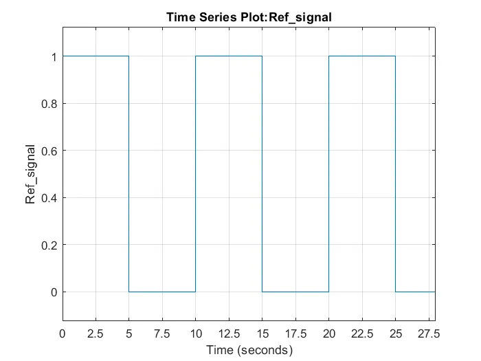
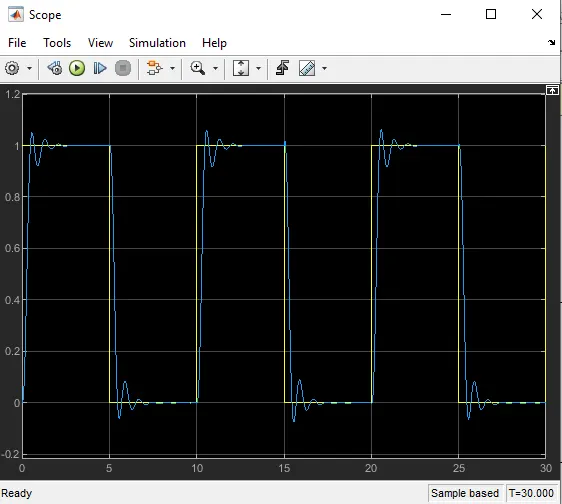
The reference signal is shown in the following figure.
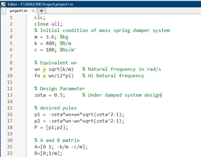
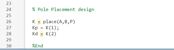
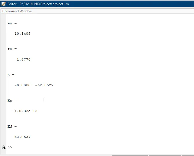
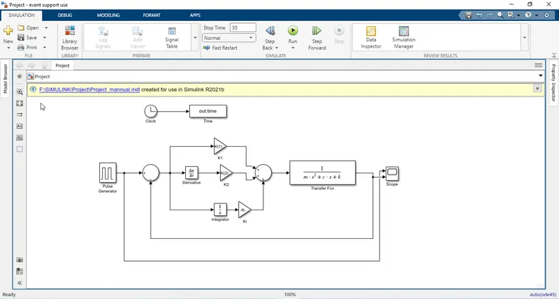
1. For the initial condition I have used value of m = 3.6 kg, k = 400 N/m & c = 100 Ns/m of mass spring damper system. So, to find equivalent wn I use sqrt(k/m) and from this I got natural frequency fn = wn/(2*pi) in Hz. Here I am using zeta = 0.5 as under damped system.
2. From sources library clock block and step block are selected and dragged to blank model.
3. A scope block is dragged from sink library to blank model to see the result of step function. From math operations drag sum block and gain blocks are dragged to blank modal. The gain block helps to set the gain to a desired value to multiply the input with.
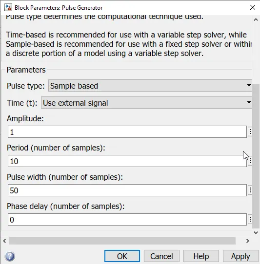
4. From source library I drag pulse indicator and change the reference value.
5. From continuous library the integrator block is dragged to blank block which allows to set the initial condition to use as the constant of integration and also transfer function is dragged to calculate m , k , c in this I use formula 1/(m.s^2+c.s+k). The blocks are connected with selection of first block and control plus clicking the second block.
6 . Now select "Model settings" from Modeling menu to allow user to enter start and stop times for the simulation.
7. After creating and connecting blocks save it and the 'Run' bottom is selected to get desired result.
8. Here I have created a manual PID controller to see result. As a result here I used for three cycle and I found overshoot, undershoot in spring mass damper system.
PID Controller Automatic:
1. For the initial condition I have used value of m = 3.6 kg, k = 400 N/m & c = 100 Ns/m of mass spring damper system. So, to find equivalent wn I use sqrt(k/m) and from this I got natural frequency fn = wn/(2*pi) in Hz. Here I am using zeta = 0.5 as under damped system.
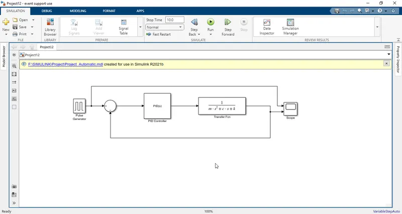
2. A scope block is dragged from sink library to blank model to see the result of step function. From math operations drag sum block is dragged to blank modal.
3. From source library I drag pulse indicator and change the reference value.
4. From continuous library transfer function is dragged to calculate m , k , c in this I use formula 1/(m.s^2+c.s+k). The blocks are connected with selection of first block and control plus clicking the second block.
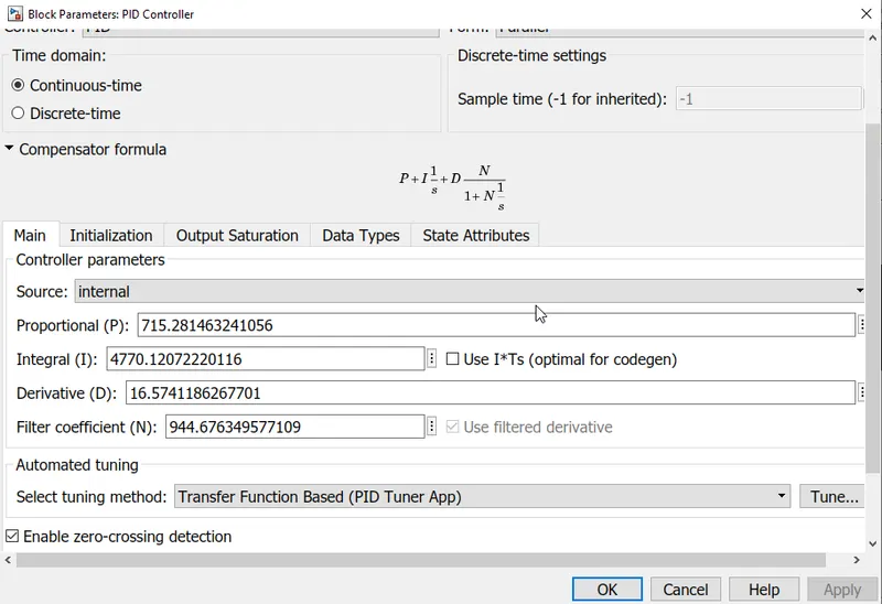
5. Here Proportional (P), Integral (I) & Derivative (D), PID controller is being dragged from continuous library which act as Automatic controller.
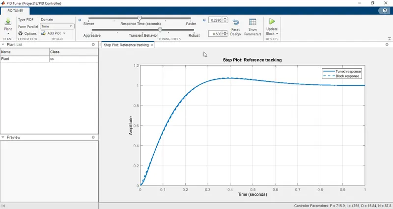
6. From PID controller I will use tuner to get the value of PID. From there I need to adjust transient behavior and response time.
7. After adjustment I have matched both the solid curve and dotted curve to obtain Kd, Kp, Ki.
8 . Now select "Model settings" from Modeling menu to allow user to enter start and stop times for the simulation.
9. After creating and connecting blocks save it and the 'Run' bottom is selected to get desired result.
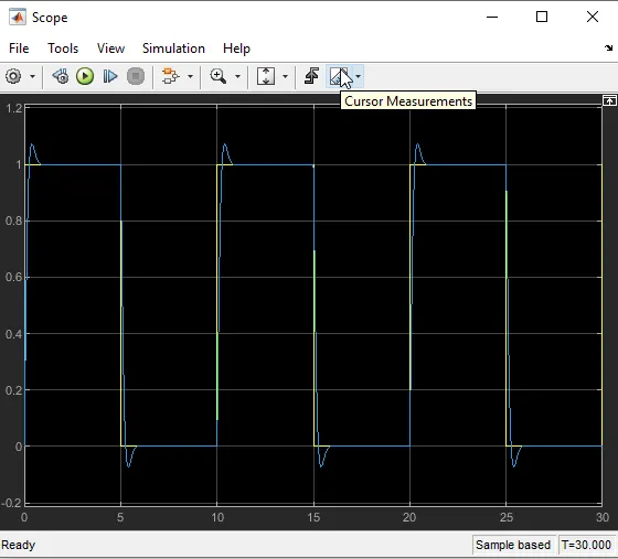
10. Here I have created a Automatic PID controller to see result. As a result here I used for three cycle and I found overshoot, undershoot in spring mass damper system.