Project on Development of TFT Cluster Speedometer Software Component
Aim : To Develop the Simulink model based on the given requirements and also create SLDD file and link the same to the model.And Perform the complete V and V workflow for the obtained model.
Description of Challenge :
Cluster Instrument receives the signals from other ECU via CAN bus interface. It also receives commands from the driver via steering wheel buttons. The signals are then processed by the Cluster ECU, after which the Cluster ECU may send the vehicle information to the LCD or light the LEDs and so forth, according to the results. Therefore, the Cluster ECU can be viewed as a carrier of the information flow.
1) Model Development :
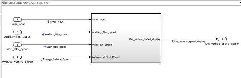
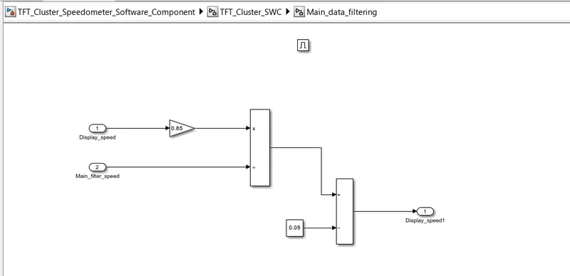
Subsystem :
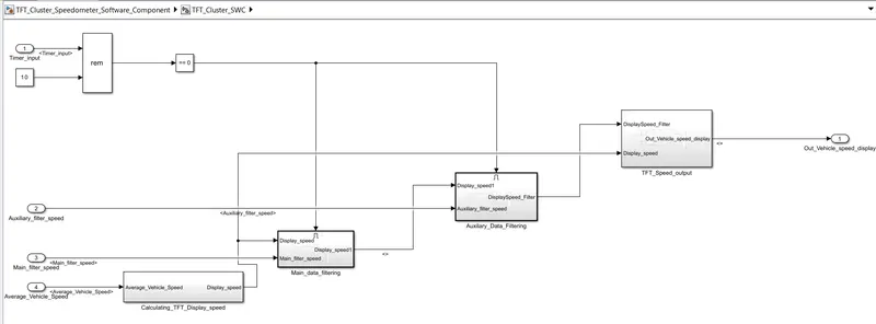
Calculating_TFT_Display_speed Subsystem :
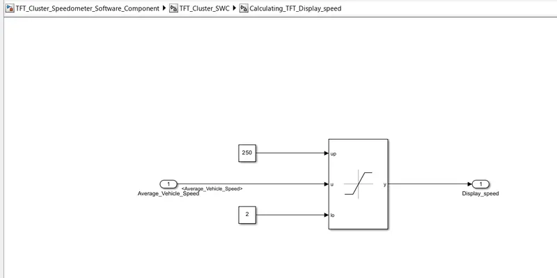
Main_data_filtering Subsystem :
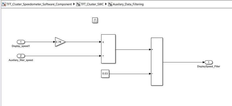
Auxilary_Data_Filtering Subsystem :
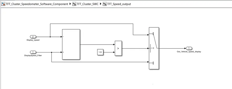
TFT_Speed_output Subsystem :
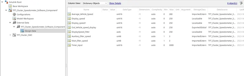
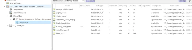
2) Simulink Data Dictionary (SLDD) :
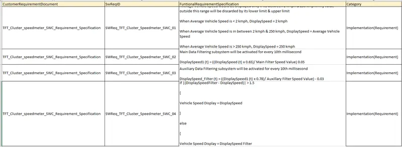
3) Requirement Tagging :
Create the Functional and SwReq File into the xls. File.
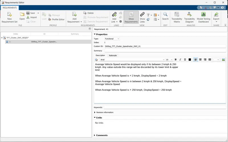
Click On the New Requirement Set :

After That Click on the Add Requirement :

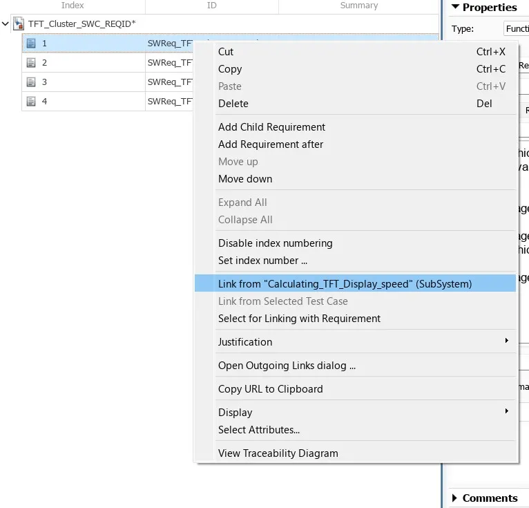
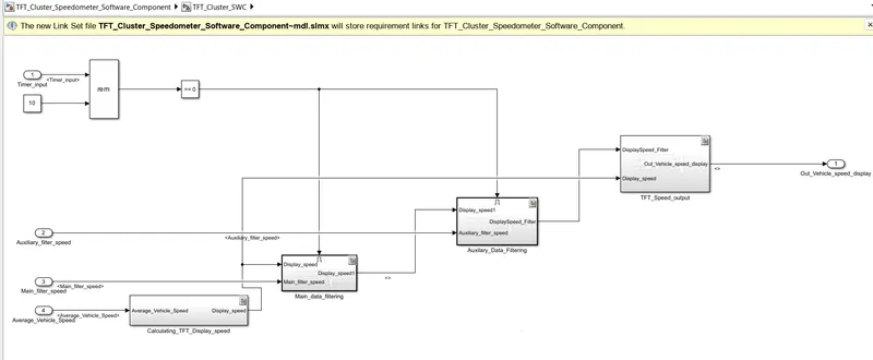
Linking the Requirement :
Link to the Subsystem
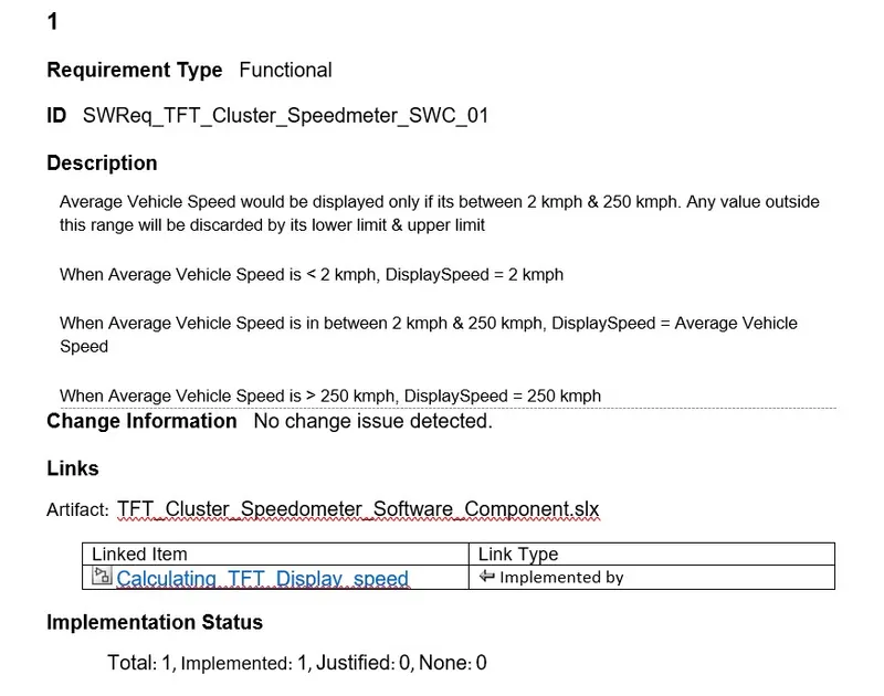
Requirement Report :
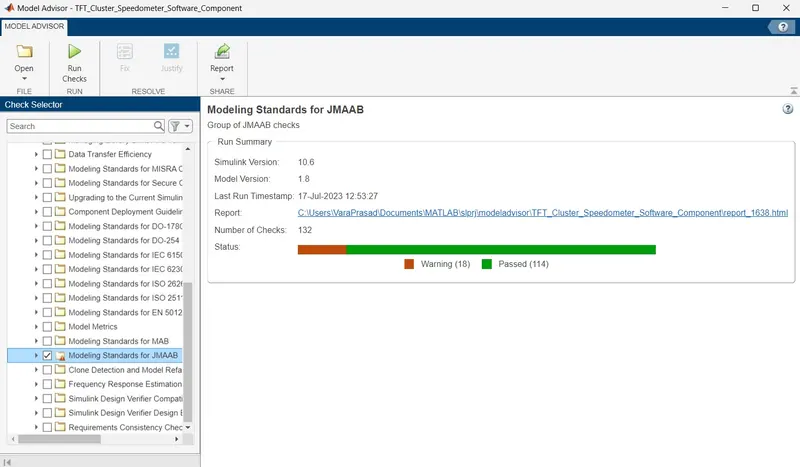
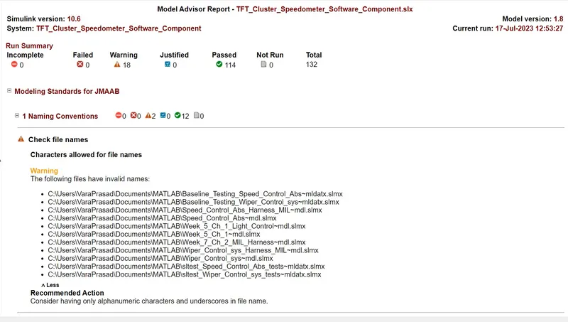
4) Model Advisor (JMAAB) :
Going to the Simulink Model >> Click on the Modelling >> Model Advisor.
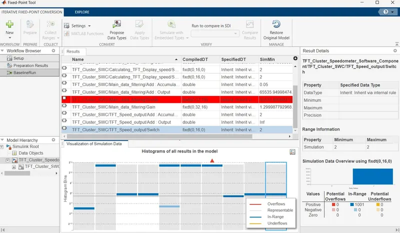
5) Fixed Point Tool :
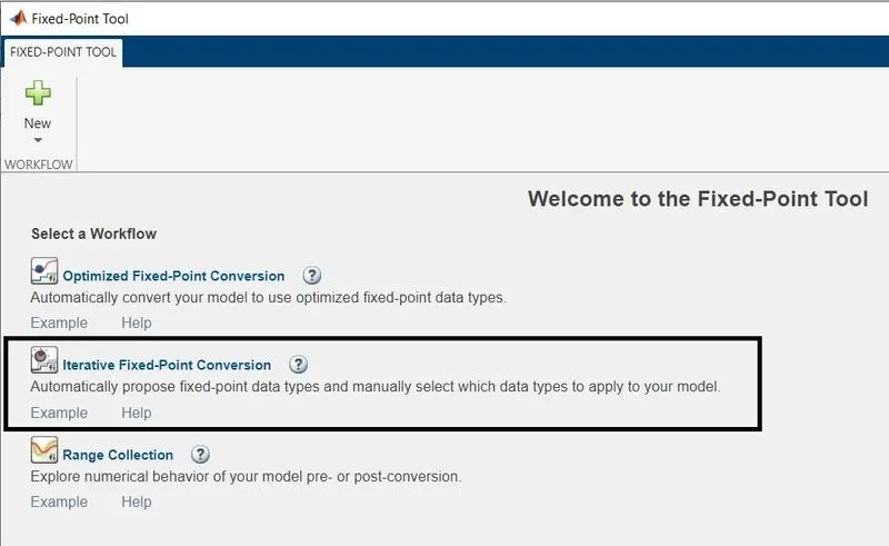
Run thee Model Error Free >> and then Click on the Fixed Point Tool >> Iterative Fixed-Point Conversion.
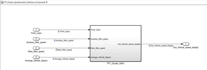
Simulation Model :
Simulink Data Dictionary(SLDD) Before Applying the Fixed point Tool:
Block Before Applying Fixed Point Tool
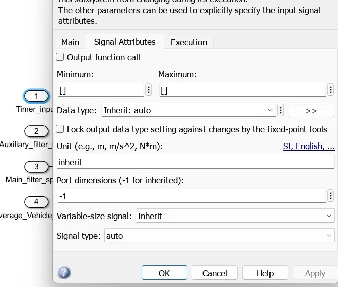
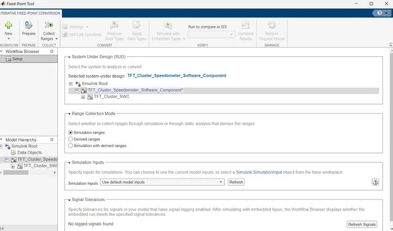
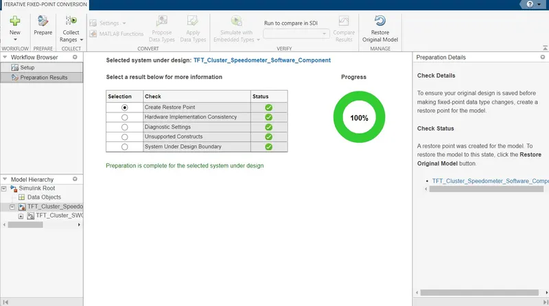
Procedure to Start the Fixed Point Tool :
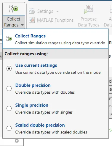
Collect Ranges using Current Settings
Simulink Data Dictionary (SLDD) After Applying the Fixed Point Tool:
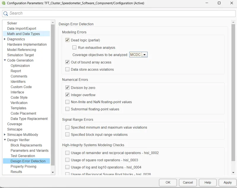
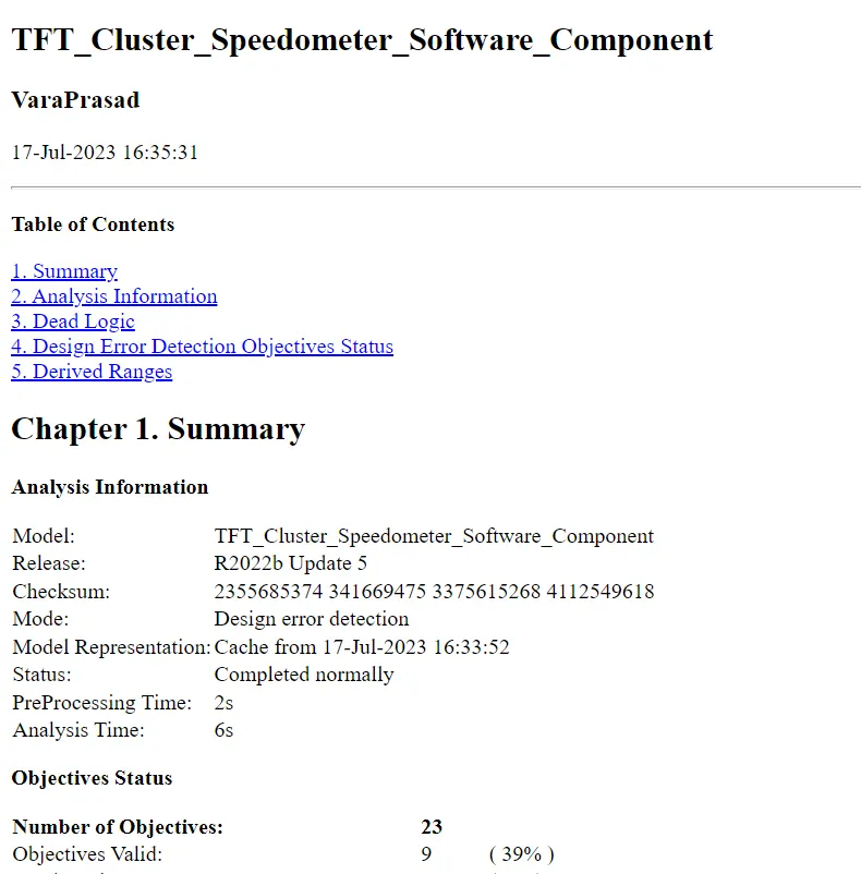
6) SLDV Design Error Detection Report :
Goto the Model >> Open the Design Verifier App >> Select the Design Error Detection >> then Click on Design Error Detection Setting.

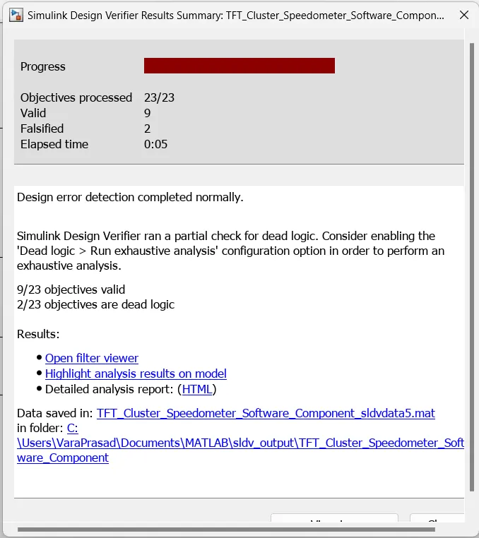
Design Error Detection Report :
7) Functional Test Cases, MIL, SIL Harness, Coverage Report :
Simulink Model :
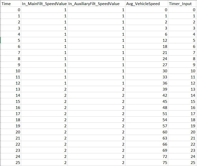
Functional Test Cases :
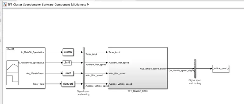
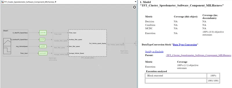
Model in Loop (MIL) :
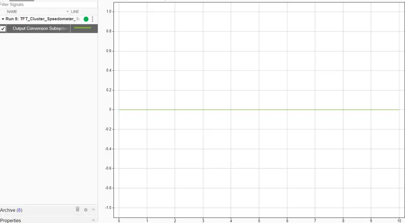
MIL Output :
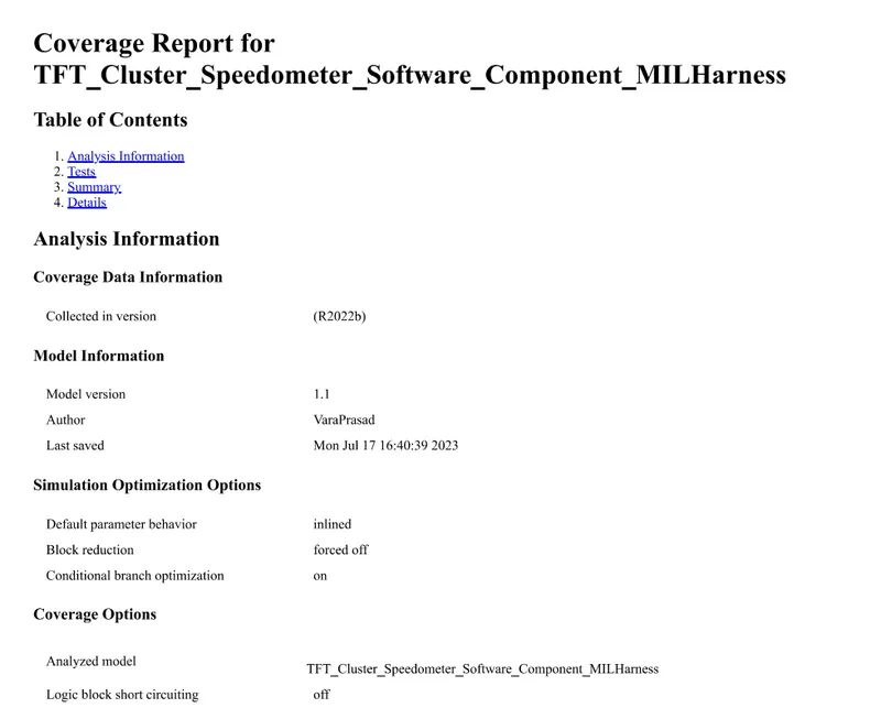
MIL Coverage Report :
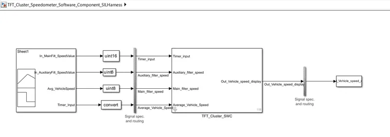
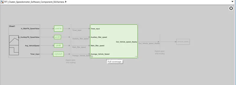
Software in Loop (SIL) :
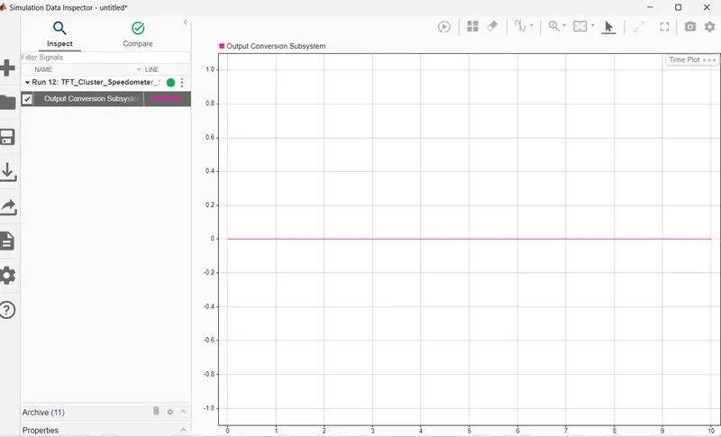
SIL Output :
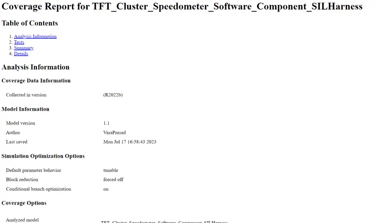
SIL Coverage Report :
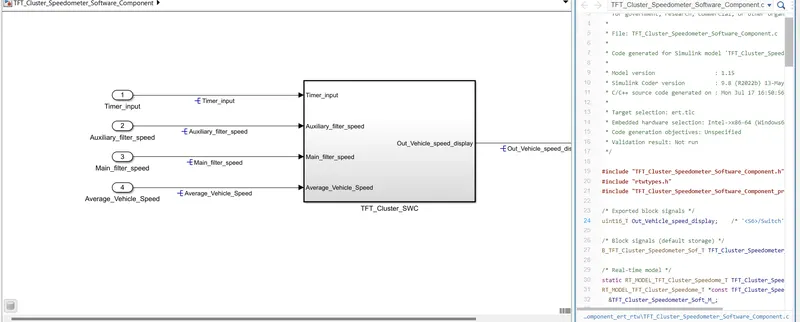
Code Generated :
8) SLDV Test Generation Report :
Goto the Model Run the model Error Free >> App >> Desgin Verifier >> Click one the Test Generation

Click on the Test Generation Setting
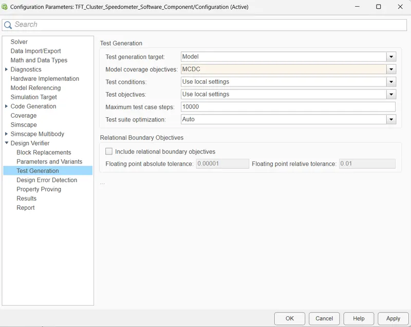
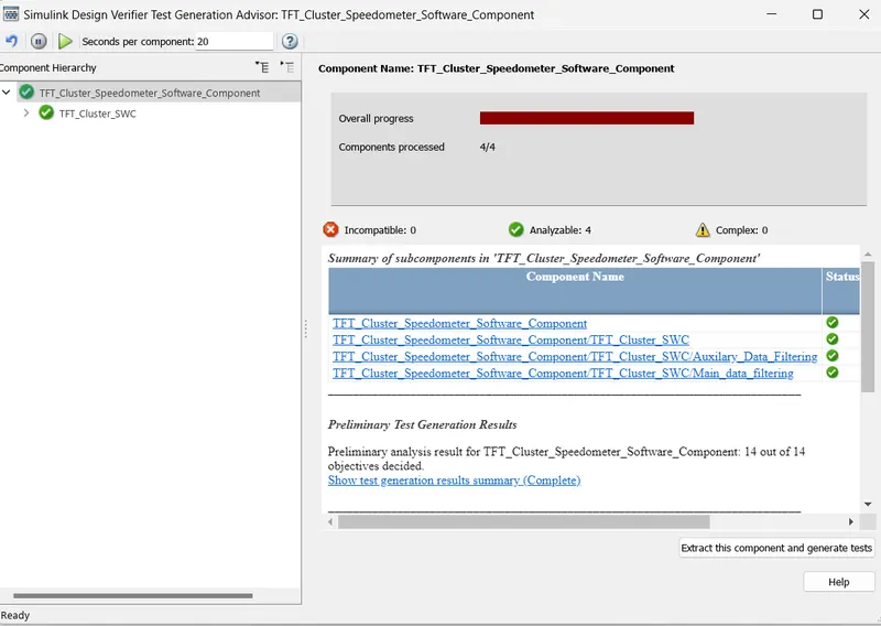
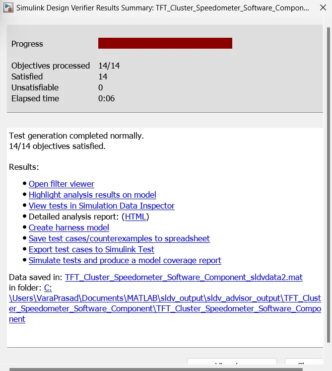
Result Summary of Test Generation :
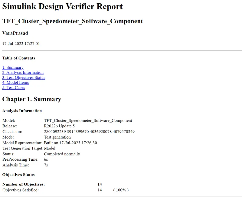
Report :
9) Auto Code Generation main .c & .h Files :
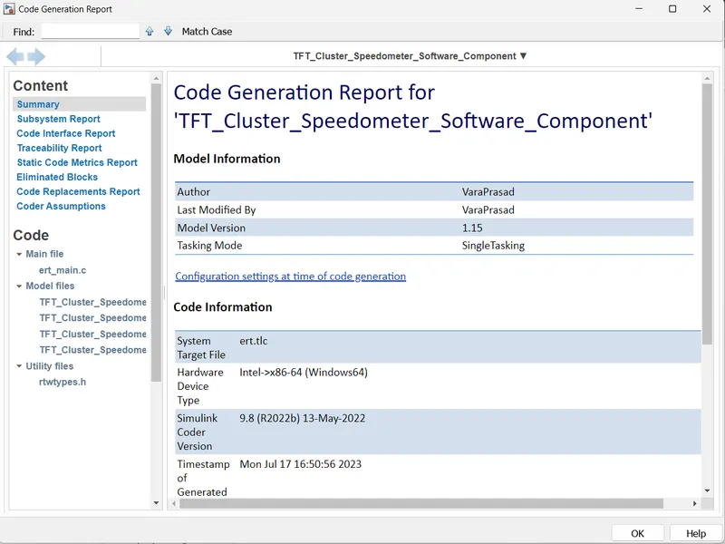
Code Report :
.c File :
10) Polyspace Analysis Report/ Output :
Procedure to Analysis the Polyspace Report
Bug Finder :
- Firstly Generated the .C code
- Initially, open the Polyspace in that new project click on start new project.
- The Project Properties dialogue box will open in that give the project name as we saved in the MATLAB,then select the location where it we need to save after that click Next or use the default location.
- Then ,it asks for the Projrct source,click on browserand select the folder where th .c file are generated then optionally we can add the include folder then clock on finish,the polyspace environment will open.
- In the configuraton settings option called Target & compiler select the source code language as c,change the target processor as X86_64.
- In the coding standards & code Metrics in that enable the check MISRA C:2004 also select the calculate the code metrics option
- After that go to bug finder analysis under that select the default one.
- Go to reporting enable the generate report option and ouput formet as PDF or any file we need
- Finally save the polyspace and run the Bug Finder.
Code Prover :
- Befour going to the Code Prover First setup the Configration setting.
- In Configuration go to the Code prover verification and under code prover verification option.
- Click on the Check Behavior and Enable the option (i,e Allow Negative Operand for left shifts).
- and also click on the Consider Non-Finite floats.
- Then After you go to the Precision
- In Precision Select the Precision level -2 and Verification Level is Software Safety Analysis Level-2.
then After Click on Save Botton the Configration setting will be save.
then After We Run the Code Prover. - And After Click on the Dashboard option and see the Results.
11) Test Generation Report- Baseline and Back to back Testing :
Baseline Testing :
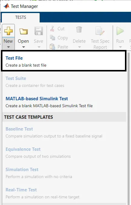
Run the model>> goto the Simulink Test >>Click on the Simulink Test Manager >> then Click on New >> Test File>> Create Test Name.


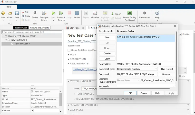
Click on the Requirement
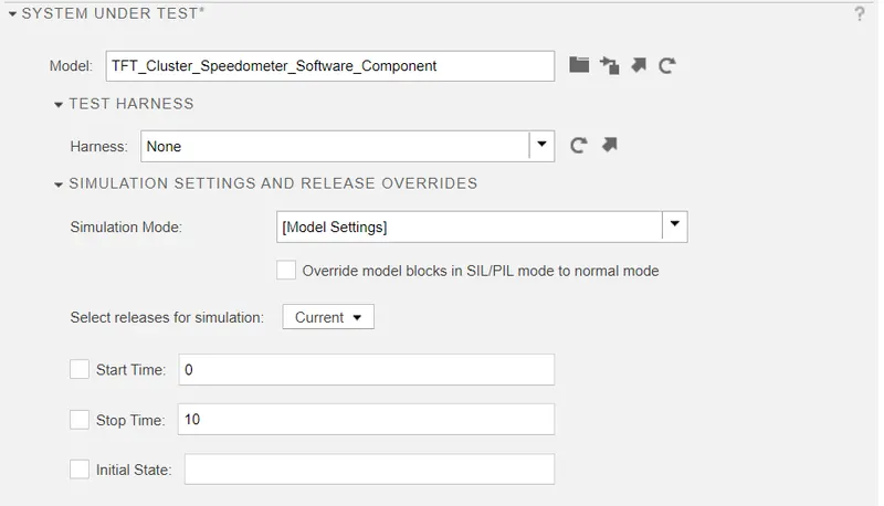
then after Click one the System Under Testing
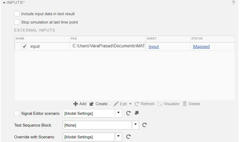
Click on the Input
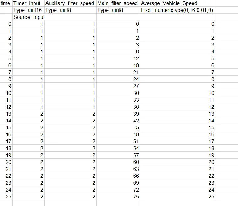
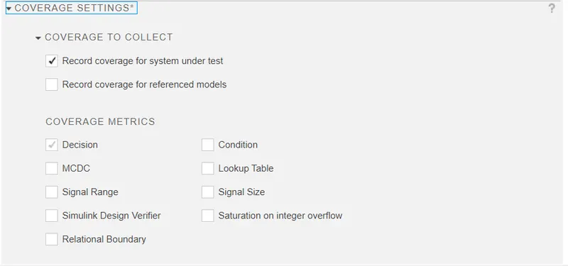
Click on the Coverage Setting >> Click on Enable Option.
then After Save and Run it.
Results :
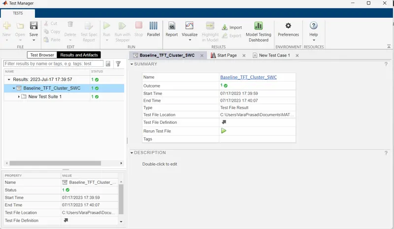
Baseline Criteria Output :
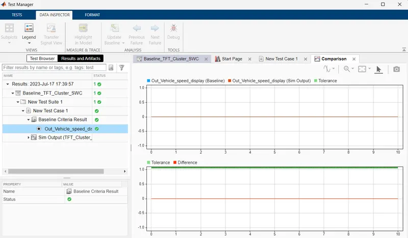
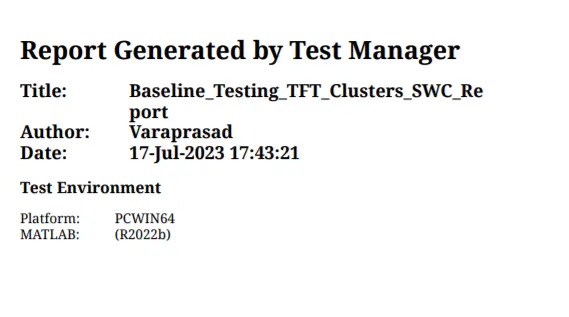
Baseline Testing Report :
Back To Back Testing :
Click on the Simulink Test Manager
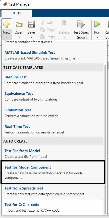
Click on New
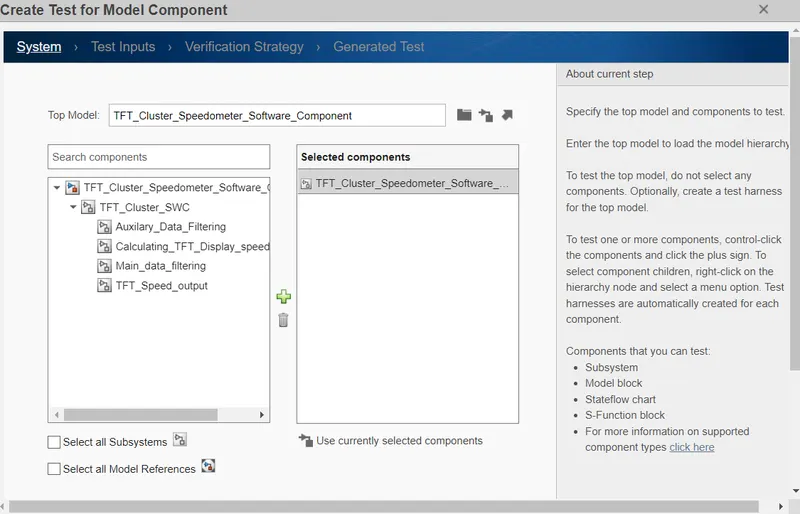
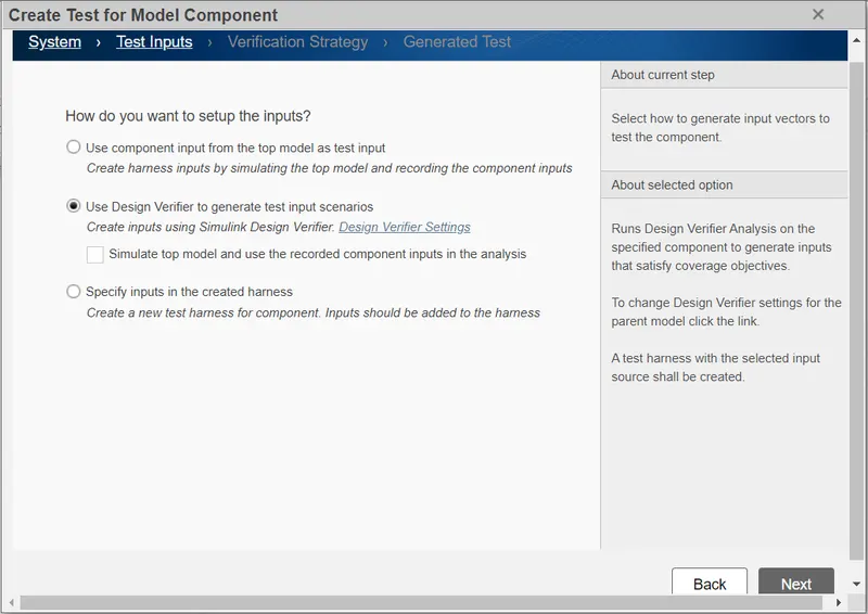
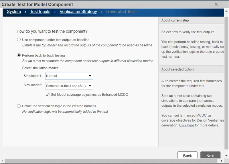
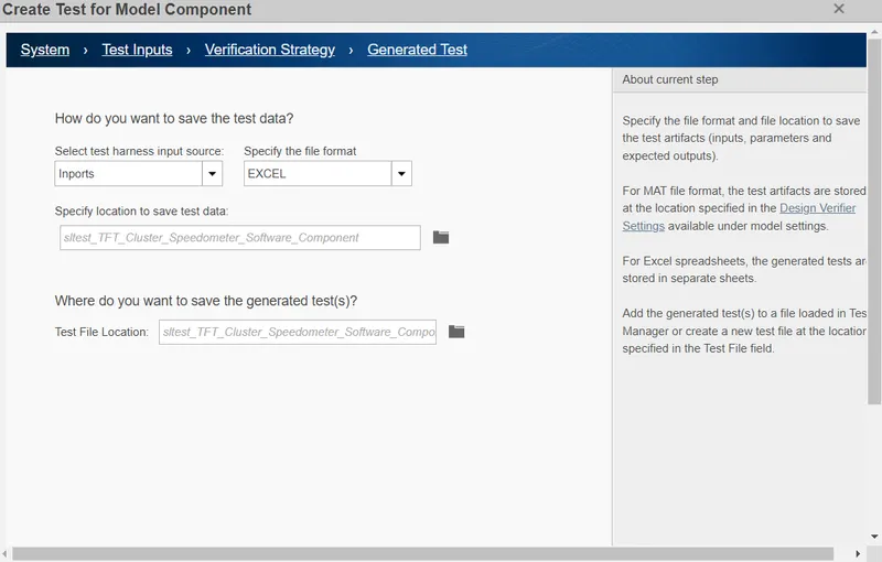
Generated MIL And SIL Model :
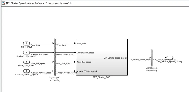
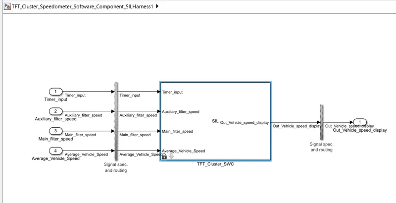
Click on the Requirement
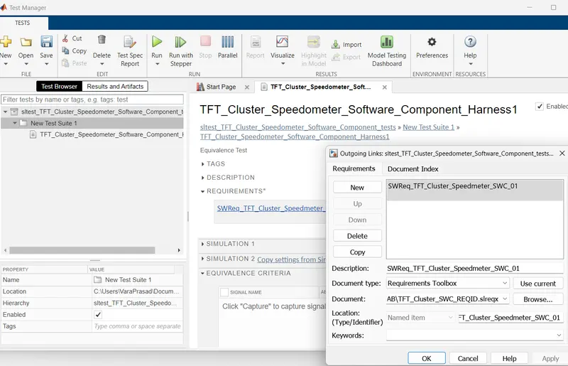
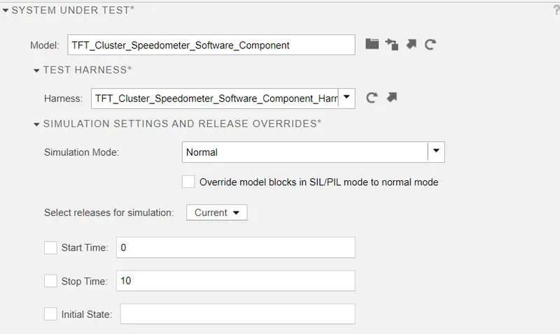
then After Click on the System under test and harness are link automatically.
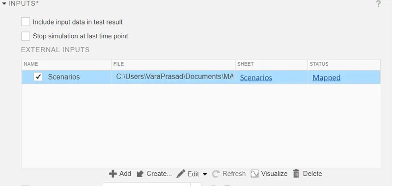
then Click on the Input and enable it.
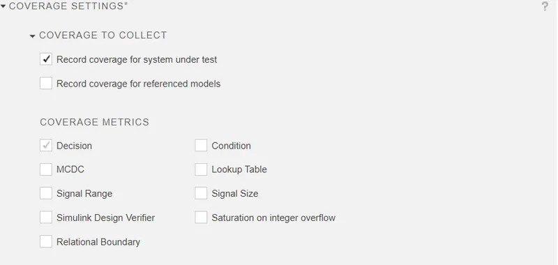
after that click on coverage Setting and Enable the Coverage.
and Save and Run it.
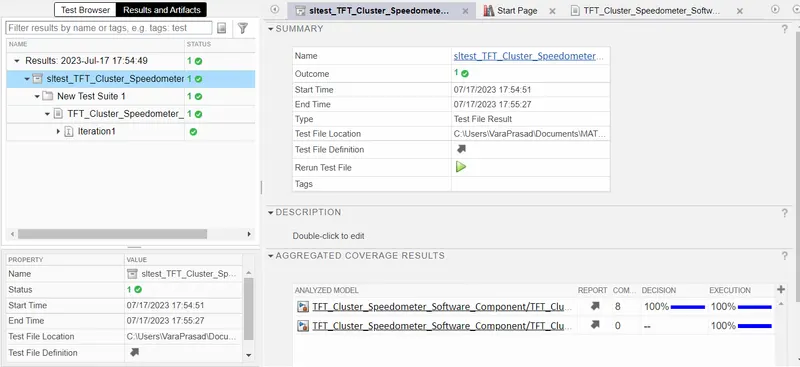
Results :
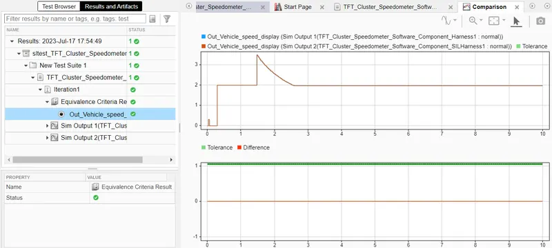
Equivalence Criteria Result :
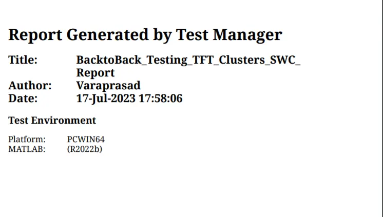
Back to back testing Report :
---------------------------------------------------------------------------------------------------------------------------------------------