Project - Analysis of a practical automotive wiring circuit
1. Identify each of the major elements in the above automotive wiring diagram.
Ans. Following are the major elements in the above autmotive wiring diagram:
- Battery,
- Starter,
- Ignition Coil,
- Distributor,
- Generator,
- Circuit breaker,
- Foot Selector Switch,
- Headlamps,
- Horn,
- Current & Voltage Regulator,
- Fuel Guage,
- Fuse,
- Ammeter,
- Tail Lamps,
- Dome Lights,
- Parking lamps.
2. Explain the purpose and working of any three elements briefly.
Ans.
Battery
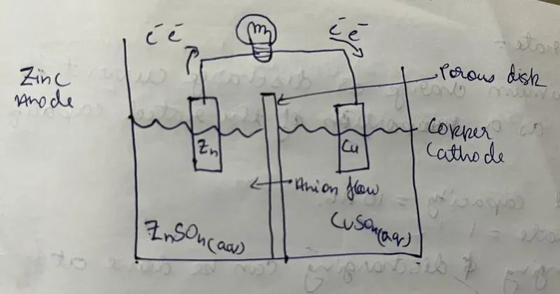
Battery Definition:
- A Battery is an energy storage device which stores electrical energy in the form of chemical energy.
- This chemical energy can be converted to electrical energy whenever required.
- Chemical reactions in a battery consists of flow of electrons between the electrodes through an external circuit.
- This flow of electrons brings about an electric current which can be used for performing work.
Major components:
- Casing: Provides shape, structural rigity and an enclosure to the internal components of a battery.
- Electrolyte: An electrolyte is the medium which facilitates the flow of ions in a battery.
- Electrodes:Electrodes are of 2 types:
- Anode: it is the negative electrode. It releases electrons and gets oxidised during the electrochemical reaction.
- Cathode: it is the positive electrode. It gains electrons and gets reduced during the electrochemical reaction.
- Terminals: Terminals connect the battery electrodes to the external circuit.
- Separator: Separator is a porous membrane that separates the anode and cathode.
Working:
- Discharging:
- During the electrochemical reaction in the battery, there is a accumulation of electrons at the anode which results in an electrical imbalance between the anode and cathode.
- To gain electrical stability, these electrons tend to rearrange themselves.
- The electrons move towards the area which is lacking electrons i.e. cathode.
- The electrolyte refrains the electrons to move towards cathode until an external circuit is connected to the terminals.
- Once an external circuit (such as the bulb in diagram) is connected to the terminals, the electrons flow towards the cathode and then through the electric circuit, this lighting the bulb.
- This electrochemical reaction in the battery continues until there are electrons available in the Anode and the supply of electrons is stopped. This shows that we have a limited amount of power from a battery.
- Charging:
- While charging, electrons are provided to the battery from an external source.
- This reverses the reaction, bringing the anode and cathode to their original state.
- Once the anode and cathode are fully restored, the battery can again be used as a source of electrical energy.
Generator:
Definition:
- A generator is a device that converts mechanical energy to electrical energy.
- There are two main types of generator:
- AC Generator: Generates AC current. It is also called as an alternator. It can generate 1-Phase or 3-Phase AC current depending upon the type of generator and the requirements.
- DC Generator: Generates DC current.
- All Generators wotk on the Faraday's law of electromagnetic induction.
Working:
- A generator consists of a stator which is the stationary part and a rotor which is the rotating part on which the armature is attached is called as the rotor.
- Coils of conductors generally made of copper material which are tightly wound on the Armature called as armature winding or rotor winding.
- The stator consist another set of permanent magnets or conductor which is called as stator winding.
- As per Faraday's law of electromagnetic induction, when a conductor is moved through a magnetic field, it induces a flow of electric current in the conductor.
- When the rotor of a generator is rotated, it makes the conductor on the armature to move inside a magnetic field.
- This induces an electrical current in the armature.
- The amount of voltage increases with increase in the speed of armature whereas, an increased magnetic filed increases the current output.
Circuit Breaker:
Definition:
- A circuit breaker is an electrical switch which is designed to protect an electrical circuit from getting damaged due to over-current or a short circuit.
- It achieves this by interrupting the current flow if the protective relay finds the current value going beyond the breaking current value of the circuit breaker.
Working:
- There are two main contacts in a circuit breaker:
- Fixed contacts,
- Moving contacts.
- During operation, the circuit is closed by moving the contactor switch to "ON" position manually.
- This causes the fixed contacts and the moving contacts to touch each other physically and the current flows through the circuit.
- The current carrying contacts which are also known as electrodes are kept engaged to each other by using a spring.
- When a failt is detected in the system, the trip coil of the circuit breaker is energized and it disconnects the contacts from each other.
- This causes the flow of electricity to stop in the circuit and can be re-engaged manually once the fault in the system is detected and fixed.
- Few types of circuit breakers are:
- Moulded case circuit breaker (MCCB)
- Miniature circuit breaker (MCB)
- Earth leakage circuit breaker (ELCB)
- residual current circuit breaker (RCCB)
3. If the total load is 10A from battery, what should be the fuse rating?
Ans.
Given Data:
Load: 10A
Voltage: 12V
By using Power(P) = Voltage(V) * Current(I)
substituting values,
Power = 12 * 10
Power =120 Watts.
For a typical car battery, the fuse rating should be considered for 25% higher power than the actual power rating.
Therefore, power for fuse rating = 120 * 1.25
= 150 Watts
Using the formula for power and substituting new value,
Current (I) = Power (P)/ Voltage(V)
Current (I) =150/12
Current (I) =12.5A
Therefore, the fuse rating has to be 12.5 Amperes.
4. If 500W is the load, what is the voltage and capacity of battery you recommend?
Ans.
As the the recommended battery voltage is 12V and the power load is 500W,
Power(P) = Voltage(V) * Current(I),
Substituting values and formula,
Current (I) = Power (P)/ Voltage(V)
Current (I) =500/12
Current (I) =41.67 Amperes.
for finding the capacity of battery,
Capacity = Current * Time
Capacity = 41.67 Amperes * 1 hr
Capacity = 41.67 Ah
Therefore, the recommended voltage of the battery is 12V and the capacity is 41.67Ah
5. Identify any two elements which are connected parallel to each other. Why they are connected in parallel?
Ans.
The elements in parallel connection are Generator and Current & Voltage Regulator.
As the current & voltage regulator has to regulate the current and voltage coming out of the generator, they have to be at the same current and voltage level.
6. Identify any two elements which are connected in series. Why they are connected in series?
Ans.
The two elements connected in series are:
- Battery: It is connected in series with voltage and current regulator for efficient charging.
- Starter: It is connected in series with battery so that same current flows between them.