Project - Analysis of a practical automotive wiring circuit
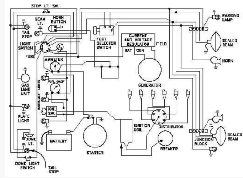
1. Identify the significant elements in the above automotive wiring diagram.
Answer.
- Gas Tank
- Fuel Gauge
- Battery
- Starter
- Generator
- Current and Voltage Regulator
- Breaker
- Distributor
- Horn Button and Horn
- Headlights, Tail Lights, Parking Lamps
- Ignition Switch
- Ignition Coil
- Junction Block
- Fuse
- Foot Selector Switch
2. Explain the purpose and working of any three elements briefly.
Answer.
- GENERATOR:- A Generator in a Car works on the principle of conversion of Mechanical Energy into Electrical Energy. When the Combustion of fuel takes place in the Engine, Mechanical Energy is produced. Therefore, the Mechanical Energy is received by the Alternator in the Generator. The stator and rotor inside the alternator work as magnets and rotate to generate the alternating current. Then the alternating current(AC) is transformed into a direct current(DC) that charges the battery.
- FUSE:-Fuses are protectors, these are the safety devices that are used to protect from high voltage damage. The fuse is made up of a thin strip or strand of metal, whenever a heavy amount of currency or an excessive current flow is there in an electrical circuit, the fuse melts and opens the circuit, and disconnects it from the power supply. Also, it works as a circuit breaker or stabilizer which protects the device from damage. In the market, many types, features, and designs of fuses are available nowadays. Their strips are made up of aluminum, copper, and zinc & it is always connected in series with the circuit to protect from overcurrent in the running cables.
- BATTERY:- In a car, the energy that is produced by the Generator is stored in the battery in the form of Direct Current(DC). The energy stored will be supplied to lights, horns, an Ignition switch (to start the process of combustion), etc. A battery is a device that stores chemical energy and converts it to electrical energy. The chemical reactions in a battery involve the flow of electrons from one material (electrode) to another, through an external circuit. The flow of electrons provides an electric current that can be used to do work. To balance the flow of electrons, charged ions also flow through an electrolyte solution that is in contact with both electrodes. Different electrodes and electrolytes produce different chemical reactions that affect how the battery works, how much energy it can store, and its voltage.
3. If the total load is 10A from the battery, what should be the fuse rating?
Answer.
Given that,
Current(I)=10A
Voltage(V)=30V [since the typical Car battery voltage is 30V ]
we know that;
Power(P)= Voltage x Current
P = V x I
P=30 x 10
P=300KW
Fuse rating=I=(P*1.5)/V
I=(300*1.5)/30
I=15A
The fuse rating is more than the maximum load of the appliance to avoid short circuits or damage to the appliance due to overflow of load. We must maintain the fuse rating 25% greater than the total load. so that the fuse rating is to be 15A.
4. If 500W is the load, what is the voltage and capacity of the battery you recommend?
Answer.
Given, Voltage of car battery (V)= 12V, Power(P) = 500W
power formula,
P = Voltage(V) x Current(I)
500 = 12 * I
I = 500 / 12
I = 41.67 Amp
So the Current from a 12V source and 500W power is 41.67Amp
let's assume we use the battery for one Day, so Time(T) = 24 hr
Then Capacity formula,
capacity = current x time
= 41.67A x 24 hr
= 1000.08 Ahr
Or for a month Time= 30 x 24 = 720Hrs
capacity = 41.67 A x 720 Hr
= 30002.4 Ah
So, I would recommend approx 30 kAh or 30002.4 Ah for a month.
5. Identify any two elements which are connected parallel to each other. Why they are connected in parallel?
Answer.
All Lights and Horns are connected in parallel to Battery so that, the failure of one element will not affect the other while they receive the same voltage.
6. Identify any two elements which are connected in series. Why they are connected in series?
Answer.
Horn and Horn switch are connected in series to Battery so that When we press the horn switch the circuit is closed and the current passes through the circuit and the horn is blown. When the horn switch is not Pressed the circuit is an open circuit so no horn is blown.