Project - Analysis of a practical automotive wiring circuit
PROJECT - ANALYSIS OF A PRACTICAL AUTOMOTIVE WIRING CIRCUIT
1. Identify each of the major elements in the above automotive wiring diagram.
Ans: The major elements in the given automotive wiring diagram are:
=> Battery
=> Starter motor
=> Generator
=> Distributor
=> Ignition coil
=> Current & voltage regulator
=> Fuse
2. Explain the purpose and working of any three elements briefly.
Ans:
=> Battery
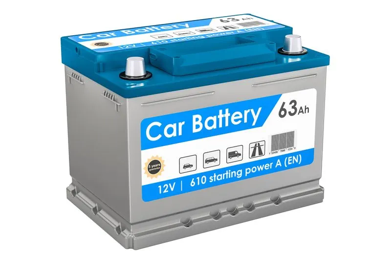
An automotive battery or car battery is a rechargeble battery that is used to start a motor vehicle. Its main purpose is to provide an electric current to the electric-powered starting motor, which in turn starts the chemically-powered internal combustion engine that actually propels the vehicle. Once the engine is running, power for the car's electrical systems is still supplied by the battery, with the alternator charging the battery as demands increase or decrease.
=> Starter motor
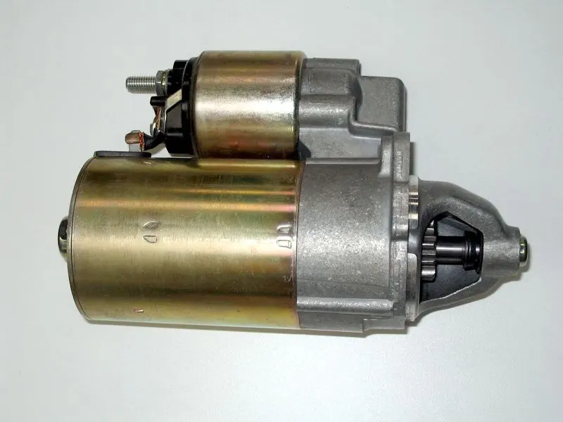
A starter motor is a device used to rotate (crank) an IC engine so as to initiate the engine's operation under its own power. Starters can be electric, pneumatic or hydraulic. The starter can also be another internal-combustion engine in the case, for instance, of very large engines, or diesel engines in agricultural or excavation applications.
=> Generator
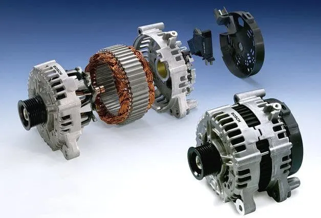
A generator is a mechanical device which converts mechanical energy to electrical energy. It is used in modern automobiles to charge the battery and to power the electrical system when its engine is running.
3. If the total load is 10A from battery, what should be the fuse rating?
Ans: If a 10A load is specified, we can use a 15A fuse. 10A is usually not a safe minimum, do to potential impulses or even small fluctuations, as a fuse is designed to not exceed the restrictions on the current, to prevent damage to the circuit.
4. If 500W is the load, what is the voltage and capacity of battery you recommend?
Ans: A battery having 100Ah capacity and 12Volts is more than enough for 500W load.
5. Identify any two elements which are connected parallel to each other. Why they are connected in parallel?
Ans: To obtain maximum illumination the lamps are connected in parallel. This creates multiple branches or pathways through which current can flow. The resistance in any given branch will determine the voltage drop and current flow through that branch and that branch alone. One of the advantages of a parallel circuit is that the various segments or pathways of the circuit can operate independently of one another. If one element goes open (breaks continuity), it won't disrupt the function of the other. So, with the arrangement an open circuit in any branch causes failure only in that one branch, the other lamps still function normally.
6. Identify any two elements which are connected in series. Why they are connected in series?
Ans: Fuses are connected in series to protect electrical circuits from dangerous overloads that could cause them to overheat, melt or catch fire, it stops the flow of current through the circuit. A blown fuse, therefore, is often an indication of an overloaded circuit or a fault such as a short that is causing excessive current flow in the circuit.
The sender in the fuel tank are connected in series so that the varying resistance in the sender will affect the position of the needle on the gauge. It varies its resistance according to the amount of fuel in the tank, and sends a small electrical current to the fuel gauge.