Project
AIM: To carry out a system-level simulation of an all-terrain vehicle using Simulink.
OBJECTIVE:
To prepare a technical report on BAJA ATV explaining model properties for the following:
- without using Lookup table
- using Lookup table
THEORY:
What Is a CVT Transmission?
A CVT transmission, or continuously variable transmission, seamlessly changes through an unending range of effective gear ratios while you drive, whereas other kinds of mechanical transmissions offer a fixed number of gear ratios and have hard shifts between each.
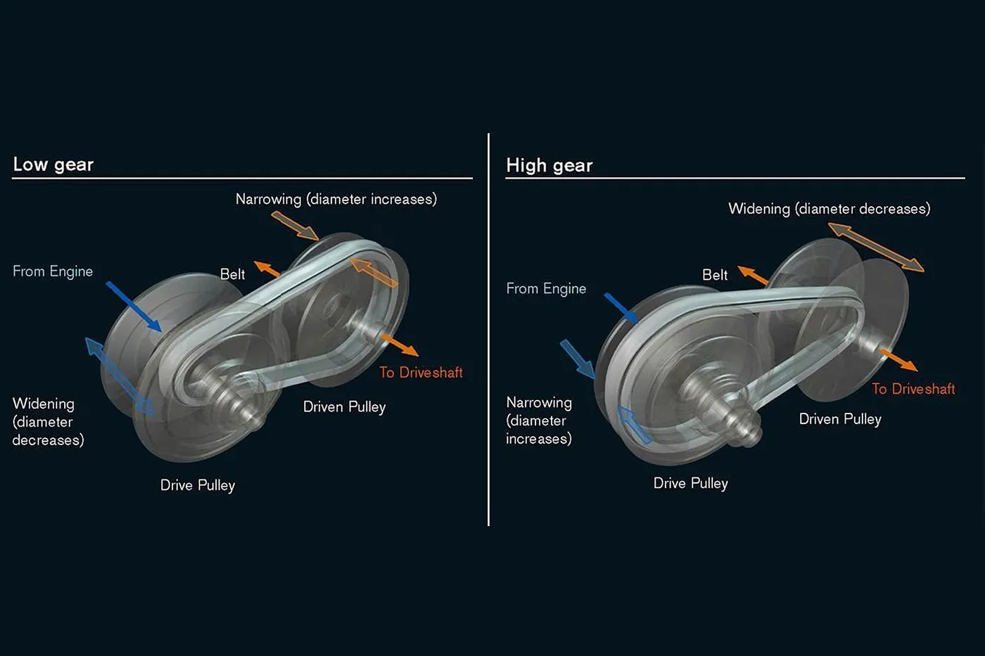
A CVT, or continuously variable transmission, seamlessly changes through an unending range of effective gear ratios while you drive, whereas other kinds of mechanical transmissions offer a fixed number of gear ratios and have hard shifts between each as explained by Certified Transmission Repair. CVT transmission systems are also known as single-speed, shiftless, and stepless transmissions.
The shiftless nature of a CVT offers unparalleled flexibility that maintains constant angular velocity regardless of output speed. Additionally, a continuously variable transmission makes accelerating smooth and offers enhanced fuel economy.
The History of the CVT
Though the CVT only recently gained popularity, with new innovations offering greater efficiency, the design has existed for centuries — Leonardo DaVinci designed the first CVT in 1490, though it wasn't officially patented until 1886 by Daimler and Benz.
The first time the CVT gained notoriety was in 1910 when Zenit motorcycles built a CVT model that was so efficient it got banned from hill-climbing competitions. By the late 1980s, the CVT entered the mainstream, thanks to Subaru. In the modern day, almost every manufacturer has at least one model with a continuously variable transmission.
How Does a CVT work?
While a traditional transmission uses a wide variety of intricate parts to shift between a range of preset gears, most CVT systems work through a pulley system. In short, this system consists of cones at each pulley connected via a chain belt. The cones can move to increase or decrease the belt diameter to change gear ratios, allow for quick shifting into the needed ratio for increased power, and boost fuel economy.
One pulley in the CVT is connected to the engine and the other directs power to the wheels. The width of these pulleys changes based on the needed power; as one gets larger, the other gets smaller. This allows a CVT to deliver strong and seamless acceleration as explained by CarFax.
There is a second, less common, type of CVT that uses a series of discs and rollers, but it operates on similar principles.
Though there are no gears in a CVT, some simulate a more traditional changing of gears. In these transmissions, the belt-and-pulley system is designed to move to preset points by using a traditional shift lever or paddle shifters on the steering wheel.
The Definition of ATV
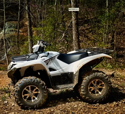
An all-terrain vehicle (ATV) is defined as a motorized off-highway vehicle designed to travel on four low-pressure or non-pneumatic tires, having a seat designed to be straddled by the operator and handlebars for steering control. ATVs are subdivided into two types as designated by the manufacturer. Type I ATVs are intended by the manufacturer for use by a single operator and no passenger. Type II ATVs are intended by the manufacturer for use by an operator and a passenger, and are equipped with a designated seating position behind the operator. Similarly, riders must also consider the various ATV sizes.
ATVs are not “one size fits all.” The ATV industry recommends all riders operate an ATV intended for their age. Youth model ATVs are designed for smaller hands and feet, and travel at slower speeds appropriate for their age.
Every ATV made by our Members comes with a warning label with the manufacturers’ minimum age recommendation. Find it. Know it. Enforce it. Click here to learn more about age and size requirements. Remember, one size does not fit all.
SOLUTION:
Part #1: BAJA ATV Model without Lookup Table
1.1 Without Dashboard
A Simulink model for the BAJA ATV Model is shown below.
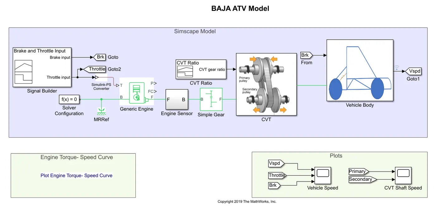
The models consist of common blocks as follows:
Signal Builder: The Signal Builder block allows you to create interchangeable groups of piecewise linear signal sources and use them in a model. You can quickly switch the signal groups into and out of a model to facilitate testing.
| Generic Engine:
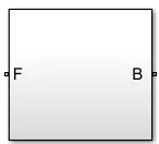
Represents a system-level model of spark-ignition and diesel engines suitable for use at initial stages of modeling when only the basic parameters are available. Optional idle speed and red line controllers are included. The throttle input signal T lies between zero and one and specifies the torque demanded from the engine as a fraction of the maximum possible torque. If the engine speed falls below the Stall speed, the engine torque is blended to zero. If the engine speed exceeds the maximum speed, the simulation stops and issues an error message. Connections F and B are mechanical rotational conserving ports associated with the engine crankshaft and engine block, respectively. Connections P and FC are physical signal output ports through which engine power and fuel consumption rate are reported. |
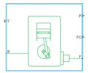 |
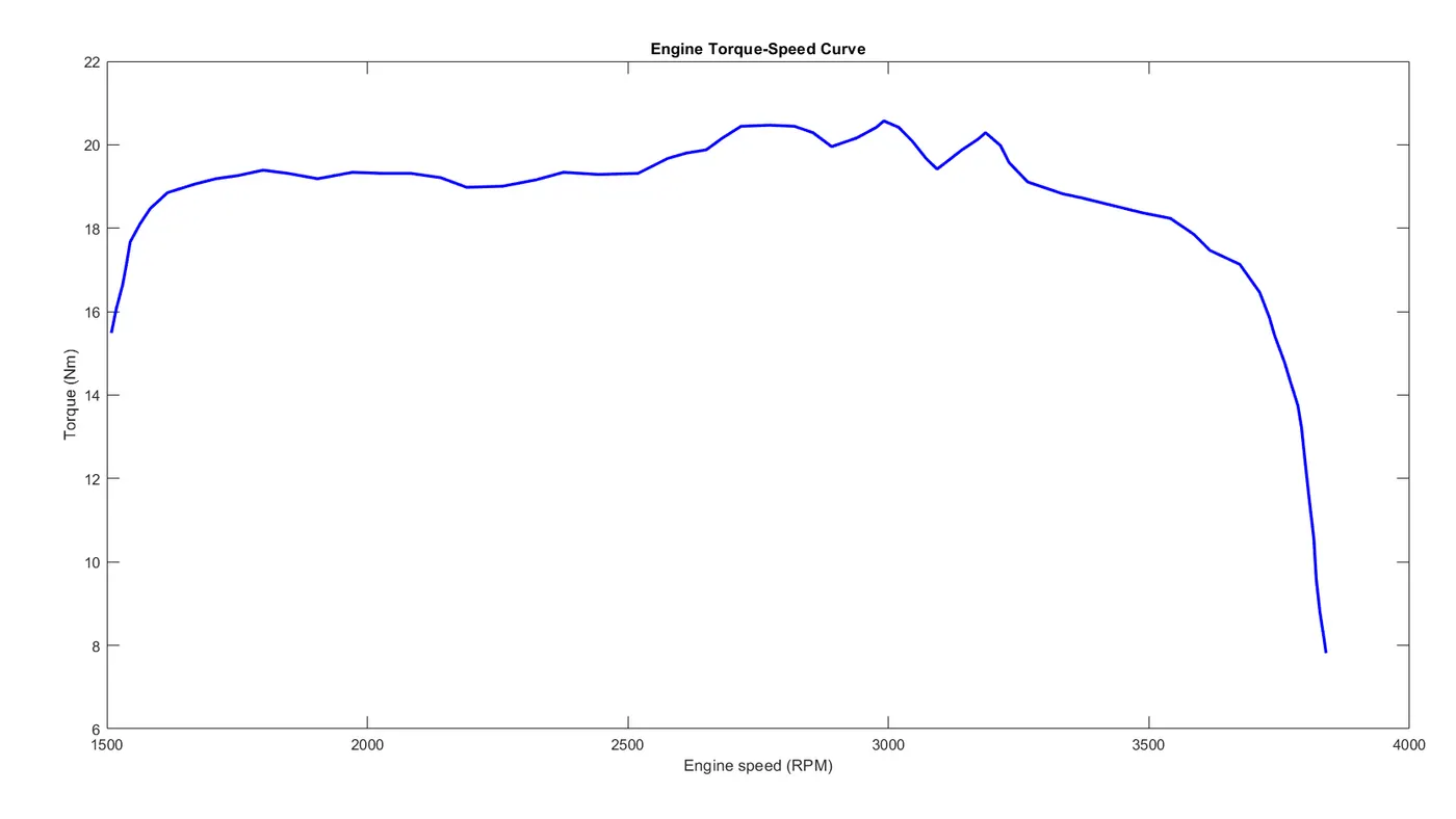
Speed vector and Torque vector are the assigned parameters.
|
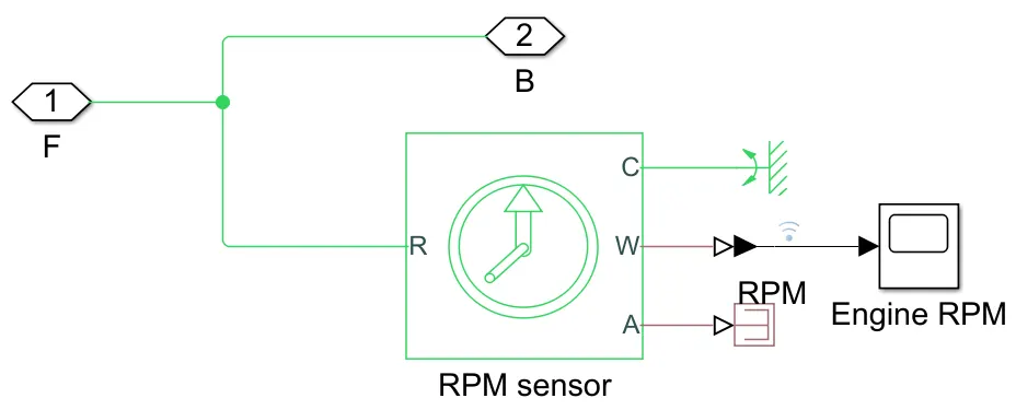
Ideal Rotational Motion Sensor: The block represents an ideal mechanical rotational motion sensor, that is, a device that converts an across variable measured between two mechanical rotational nodes into a control signal proportional to angular velocity or angle. The sensor is ideal since it does not account for inertia, friction, delays, energy consumption, and so on. Connections R and C are mechanical rotational conserving ports and connections W and A are physical signal output ports for velocity and angular displacement, respectively. |
 |
 |
|
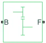
Simple Gear: Represents a fixed-ratio gear or gearbox. No inertia or compliance is modeled in this block. You can optionally include gear meshing and viscous bearing losses. Connections B (base) and F (follower) are mechanical rotational conserving ports. Specify the relation between base and follower rotation directions with the Output shaft rotates parameter. Optionally include thermal effects and expose thermal conserving port H by right-clicking on the block and selecting Simscape block choices to switch between variants. Follower (F) to base (B) teeth ratio (NF/NB): 4 |
 |
CVT Subsystem:
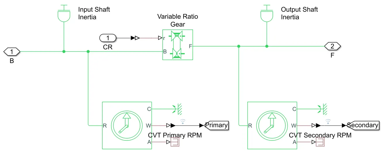
The CVT Subsystem consists of the following blocks:
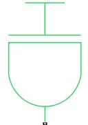
| Inertia: The block represents an ideal mechanical rotational inertia.
The block has one mechanical rotational conserving port. The block positive direction is from its port to the reference point. This means that the inertia torque is positive if the inertia is accelerated in a positive direction. |
 |
|
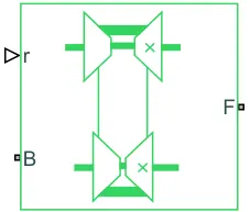
Variable Ratio Transmission: Represents a variable ratio gearbox such as implemented by mechanical belt CVT, electric, or hydraulic transmissions. The physical signal input r defines the ratio of input to output angular shaft velocities. Connections B (base) and F (follower) are mechanical rotational conserving ports. Specify the relation between base and follower rotation directions with the Output shaft rotates parameter. |
 |
Vehicle Body Subsystem:
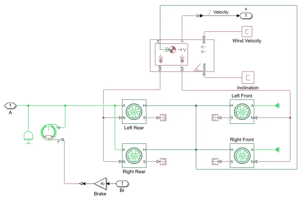
The Vehicle Body Subsystem consists of the following blocks:
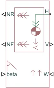
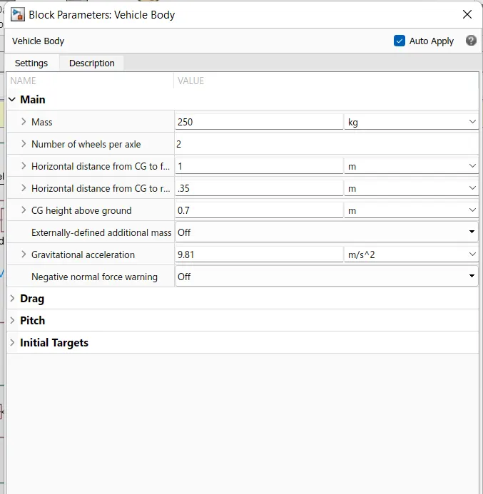
Vehicle Body: Represents a two-axle vehicle body in longitudinal motion. The block accounts for body mass, aerodynamic drag, road incline, and weight distribution between axles due to acceleration and road profile. The vehicle can have the same or a different number of wheels on each axle. Optionally include pitch and suspension dynamics or additional variable mass and inertia. The vehicle does not move vertically relative to the ground.
Connection H is the mechanical translational conserving port associated with the horizontal motion of the vehicle body. The resulting traction motion developed by tires should be connected to this port. Connections V, NF, and NR are physical signal output ports for vehicle velocity and front and rear normal wheel forces, respectively. Wheel forces are considered positive if acting downwards. Connections W and beta are physical signal input ports corresponding to headwind speed and road inclination angle, respectively. If the variable mass is modeled, the physical signal input ports CG and M are exposed. CG accepts a two-element vector representing the x and y distance offsets from vehicle CG to additional load mass CG. M represents the additional mass. If both variable mass and pitch dynamics are included, the physical signal port J accepts the inertia of the additional mass about its own CG.
 |
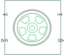
Tire: Represents the longitudinal behavior of a highway tire characterized by the tire Magic Formula. The block is built from Tire-Road Interaction (Magic Formula) and Simscape Foundation Library Wheel and Axle blocks. Optionally, the effects of tire inertia, stiffness, and damping can be included.
Connection A is the mechanical rotational conserving port for the wheel axle. Connection H is the mechanical translational conserving port for the wheel hub through which the thrust developed by the tire is applied to the vehicle. Connection N is a physical signal input port that applies the normal force acting on the tire. The force is considered positive if it acts downwards. Connection S is a physical signal output port that reports the tire slip. Optionally expose physical signal port M by setting Parameterize by to Physical signal Magic Formula coefficients. Physical signal port M accepts a four-element vector corresponding to the B, C, D, and E Magic Formula coefficients.
|
Parameters (common for all tires) are: Parameterize by: Constant Magic Formula coefficients Magic Formula B coefficient: 10 Magic Formula C coefficient: 1.9 Magic Formula D coefficient: 1 Magic Formula E coefficient: 0.97 |
 |
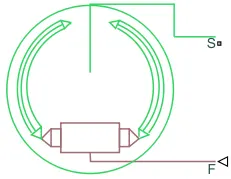
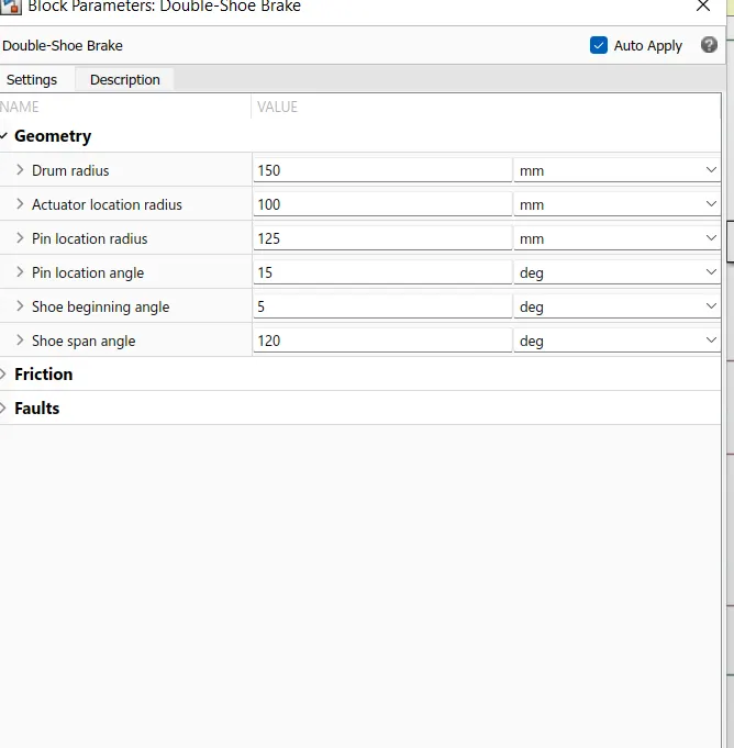
Double-Shoe Brake: Represents a brake arranged as two pivoted rigid shoes symmetrically installed inside or outside a drum and operated by one actuator. The actuator force causes the shoes to exert a friction torque on a shaft connected to the drum.
Connection S is a conserving rotational terminal associated with the drum shaft. Connection F is a physical signal port representing the force input to the actuator. Positive force creates friction torque that resists shaft rotation. Optionally include thermal effects and expose thermal conserving port H by setting Thermal port to Model.
 |
Torque vs Speed characteristics:
Input #1.1:
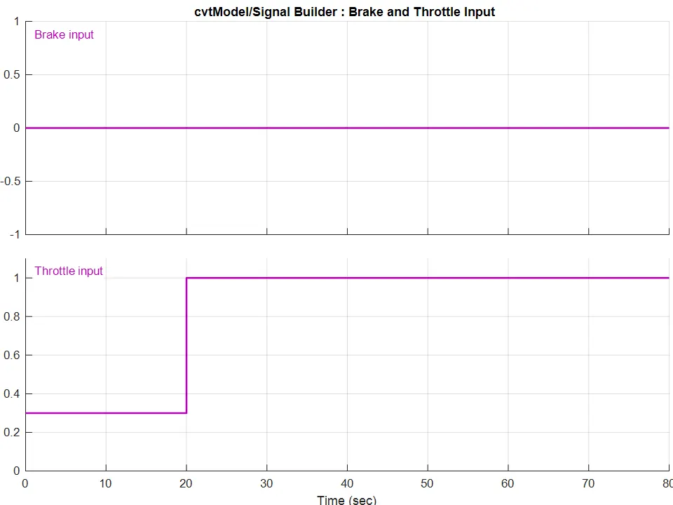
Brake and Throttle input:
Brake input is constant i.e. zero throughout the time of 80 sec.
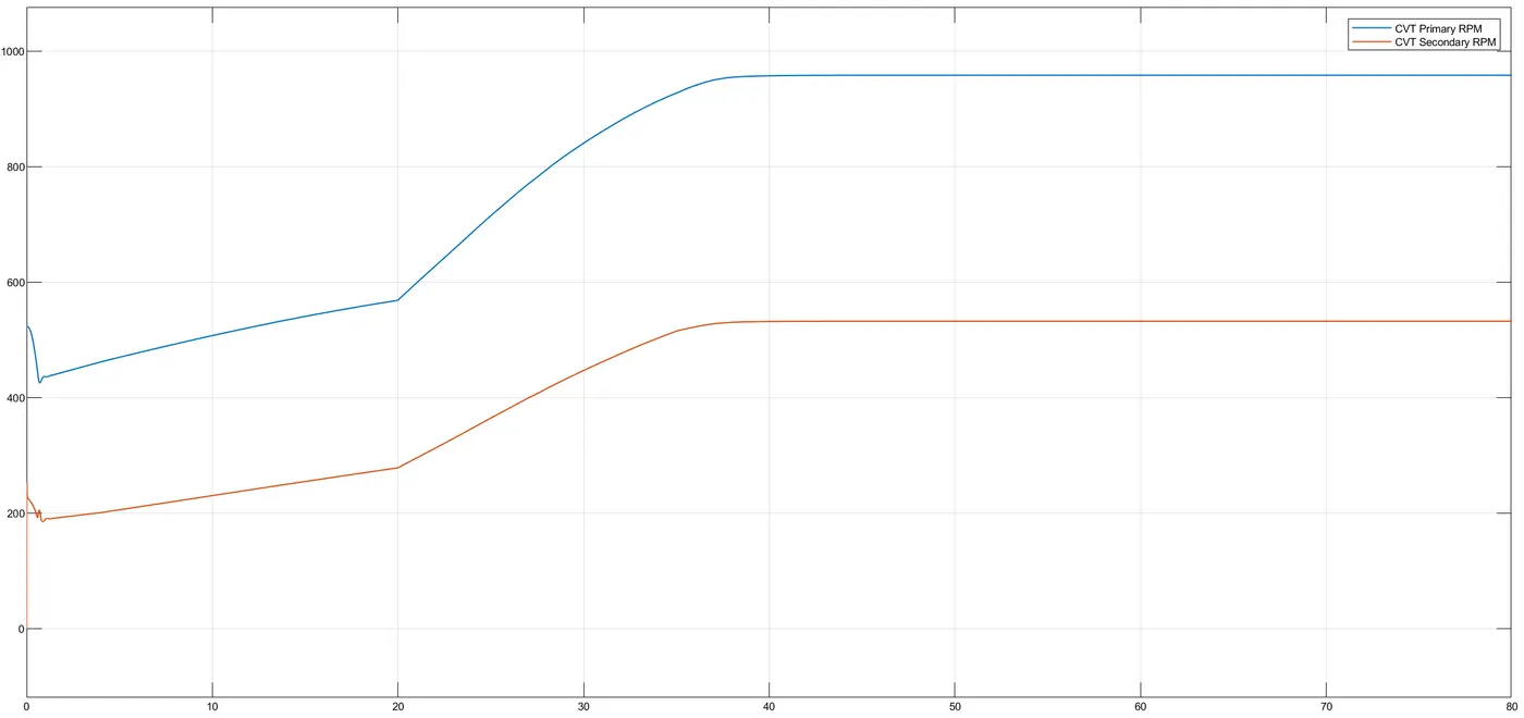
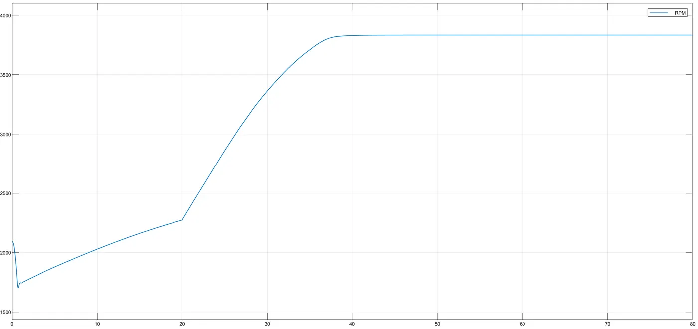
Throttle input is 0.3 for first 20 sec, accelerates to 1 at the same and remains constant throughout the remaining time till 80 sec.
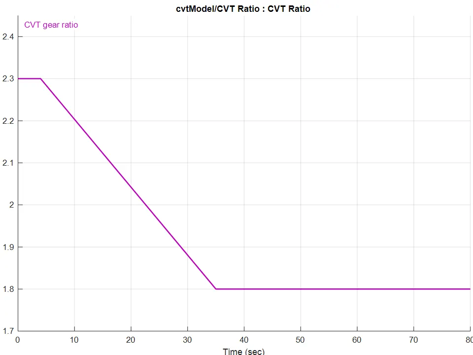
CVT Ratio:
The CVT gear ratio 2.3 for the first 4 secs, then drops down to 1.8 till 35 secs and remains constant thereafter rill 80 sec
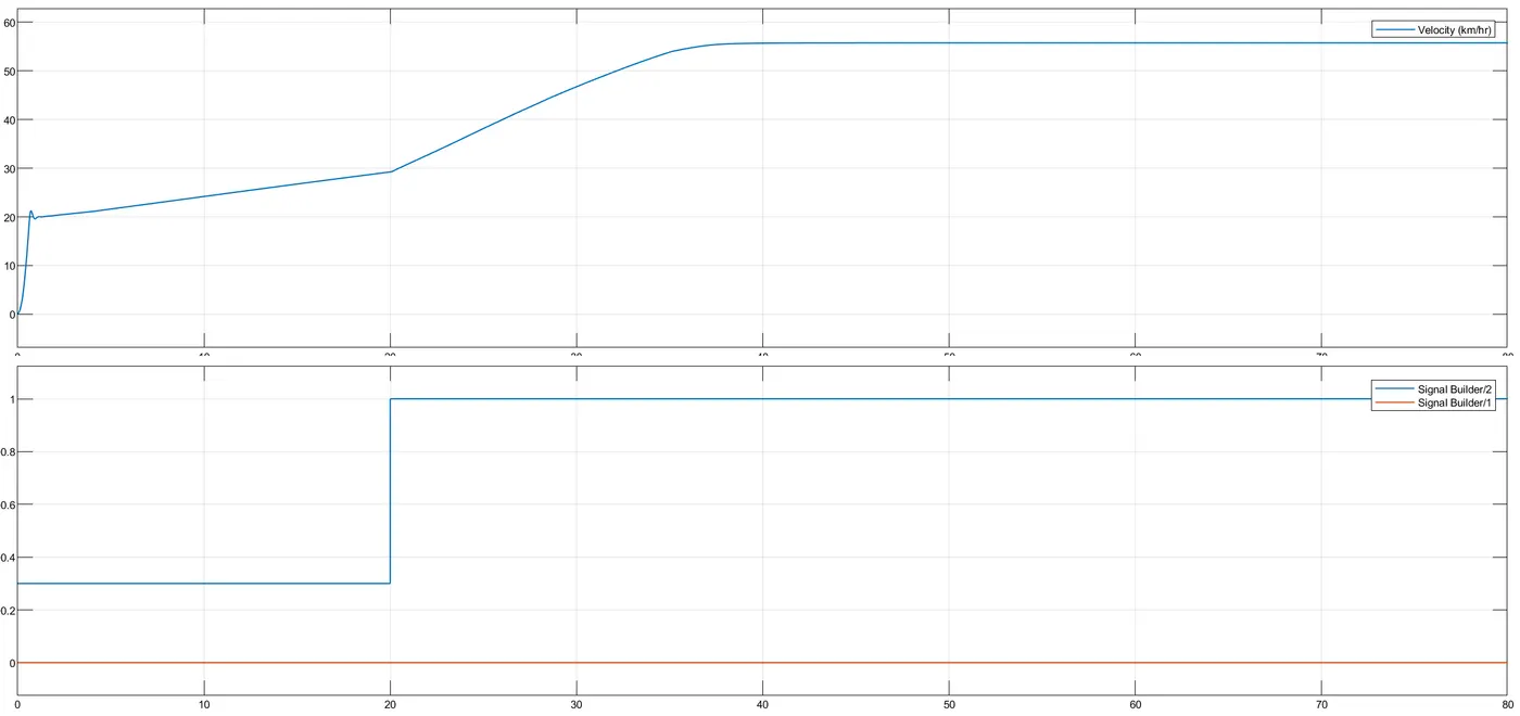
Output #1.1:
Velocity:
CVT Shaft Speed:
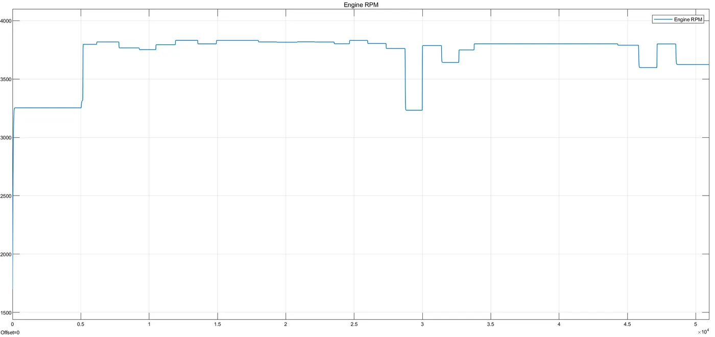
Engine Speed:
1.2 With Dashboard
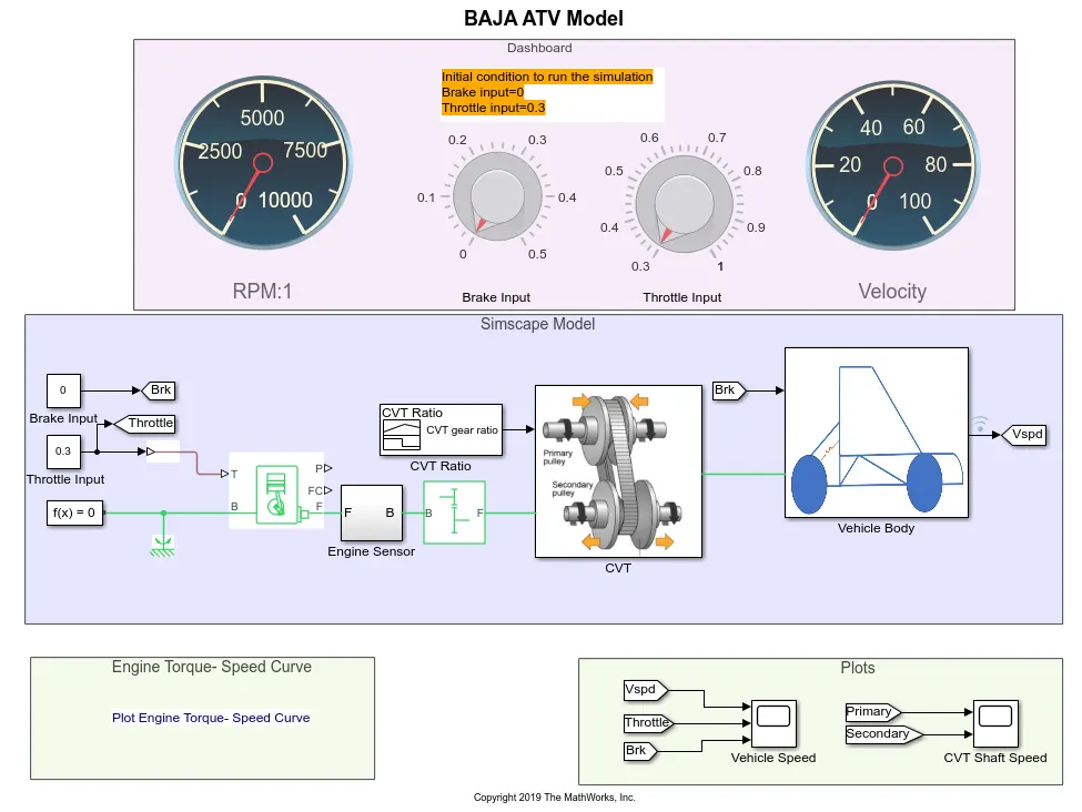
A Simulink model for the BAJA ATV Model including the dashboard is shown below. The rest of the parts and subsystems are common in the above part #1.1.
Dashboard: A dashboard (also called dash, instrument panel (IP), or fascia) is a control panel usually located directly ahead of a vehicle's driver, displaying instrumentation and controls for the vehicle's operation.
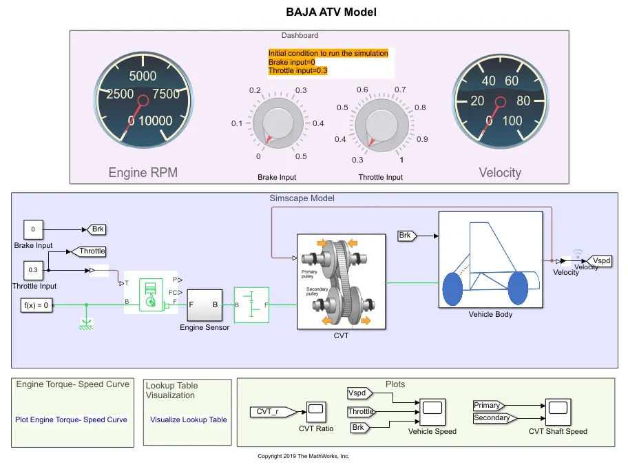
The initial conditions are as follows:
Brake Input = 0
Throttle Input = 0.3
Output #1.2:
Velocity:
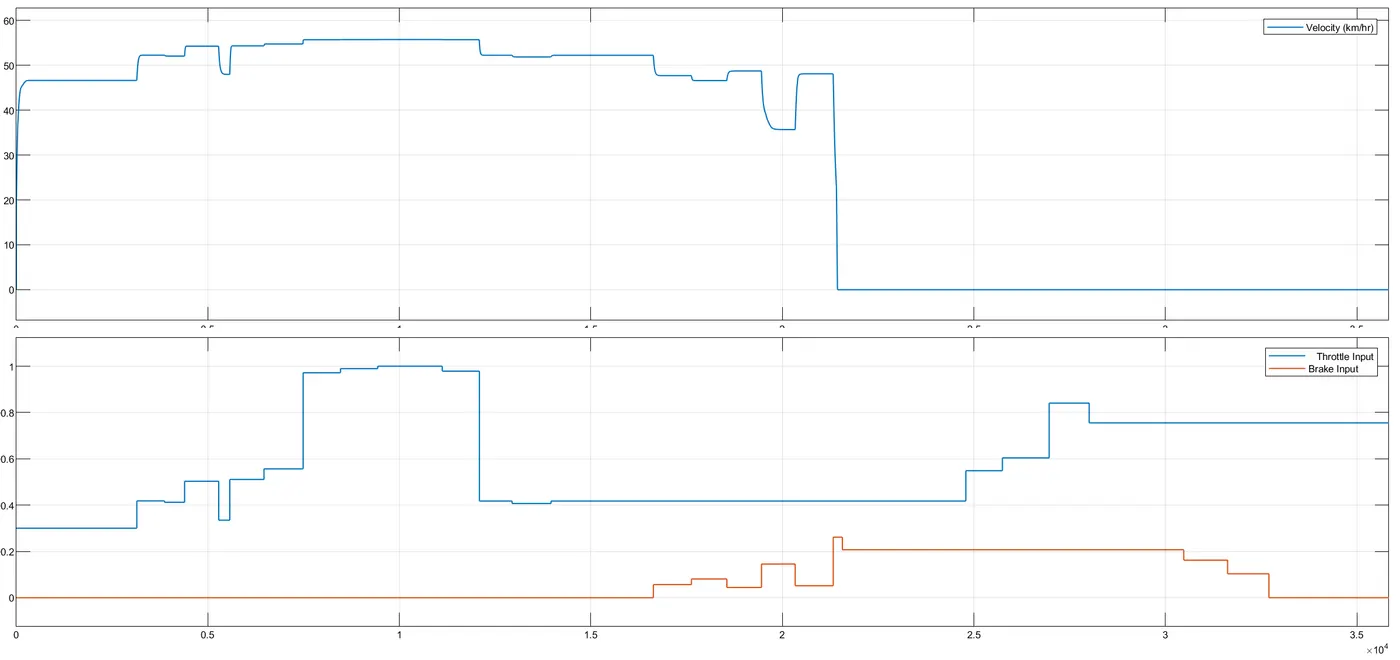
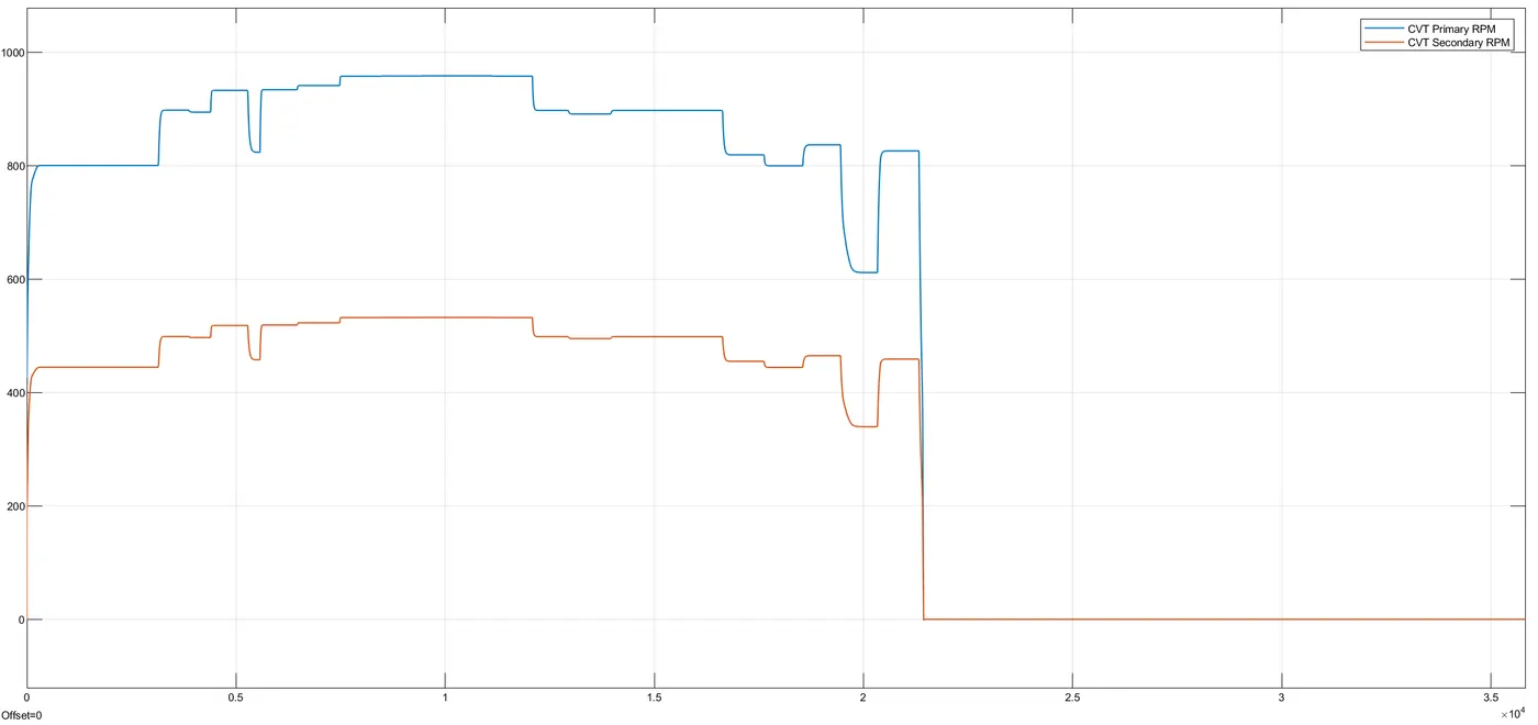
CVT Shaft Speed:
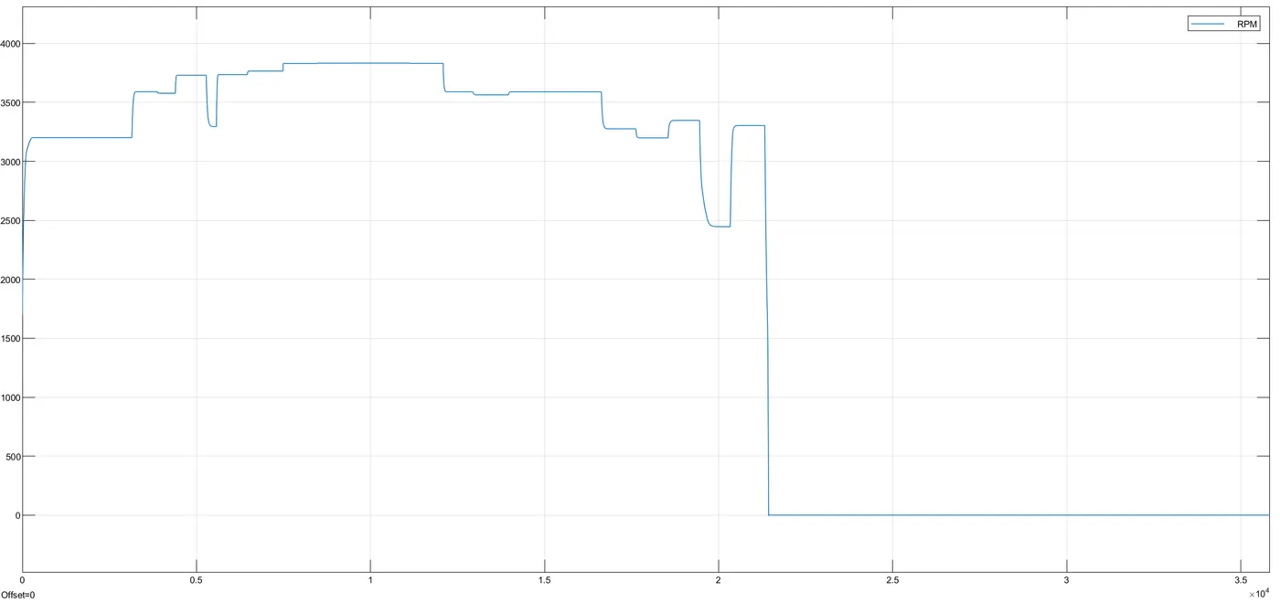
Engine Speed:
Part #2: BAJA CVT using Lookup Table
2.1 Without Dashboard
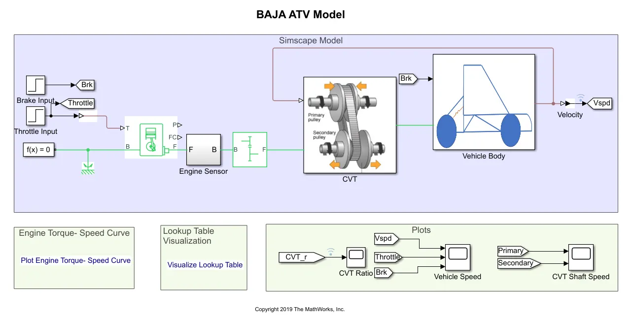
A Simulink model for the BAJA ATV Model including the Lookup table is shown below.
Lookup Table: A lookup table is an array of data that maps input values to output values, thereby approximating a mathematical function. Given a set of input values, a lookup operation retrieves the corresponding output values from the table. If the lookup table does not explicitly define the input values, Simulink can estimate an output value using interpolation, extrapolation, or rounding, where:
- Interpolation is a process for estimating values that lie between known data points.
- Extrapolation is a process for estimating values that lie beyond the range of known data points.
- Rounding is a process for approximating a value by altering its digits according to a known rule.
A lookup table block uses an array of data to map input values to output values, approximating a mathematical function. Given input values, Simulink performs a “lookup” operation to retrieve the corresponding output values from the table. If the lookup table does not define the input values, the block estimates the output values based on nearby table values.
In place of CVT ratio input, a lookup table is assigned in the models below. It needs to be loaded in the workspace having the file name as Lookuptable_data.mat
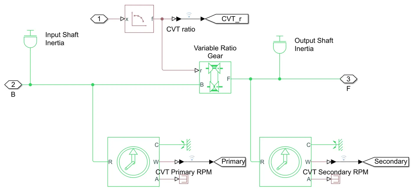
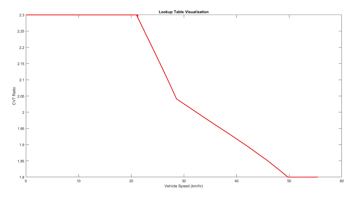
CVT Ratio vs Vehicle Speed:
0 to 20 km/hr, the CVT ratio is constant at 2.3
20 to 30 km/hr, the CVT ratio drops down to 2.03
30 to 50 km/hr, the CVT ratio drops down to 1.8
50 km/hr onwards, the CVT ratio is constant at 1.8
Input #2.1:
They are given in steps using the step block. Parameters are:
|
Brake Input: Step time: 35 Initial value: 0 Final value: 0 Sample time: 0 |
Throttle Input: Step time: 20 Initial value: 0.3 Final value: 1 Sample time: 0 |
|
Output #2.1:
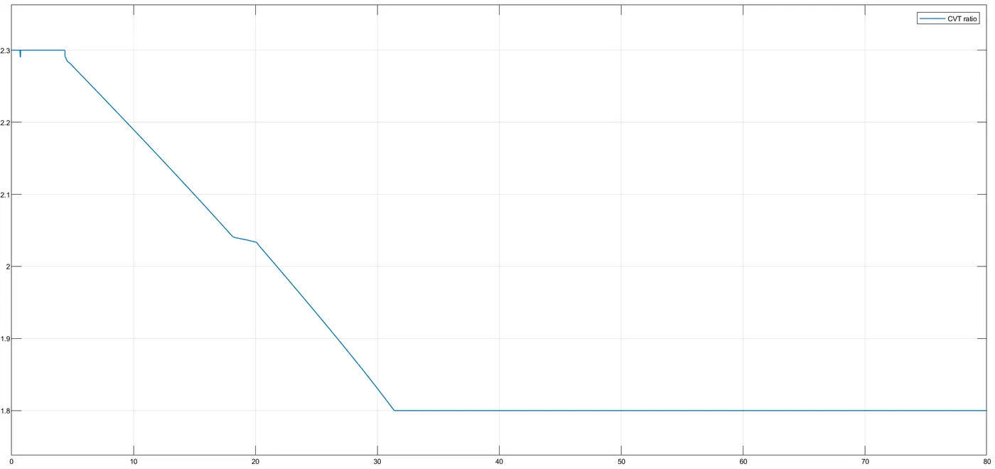
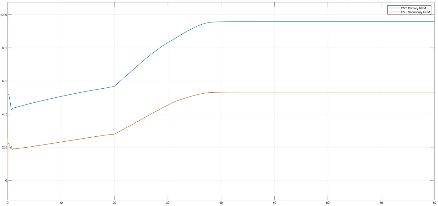
CVT Ratio:
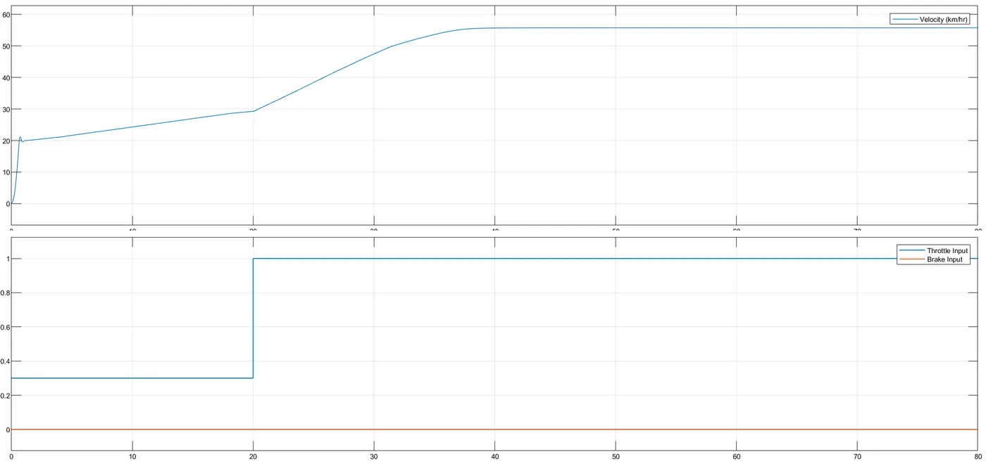
Velocity:
CVT Shaft Speed:
Engine Speed:
2.2 With Dashboard
A Simulink model for the BAJA ATV Model including the dashboard and the Lookup table is shown below.
Output #2.2:
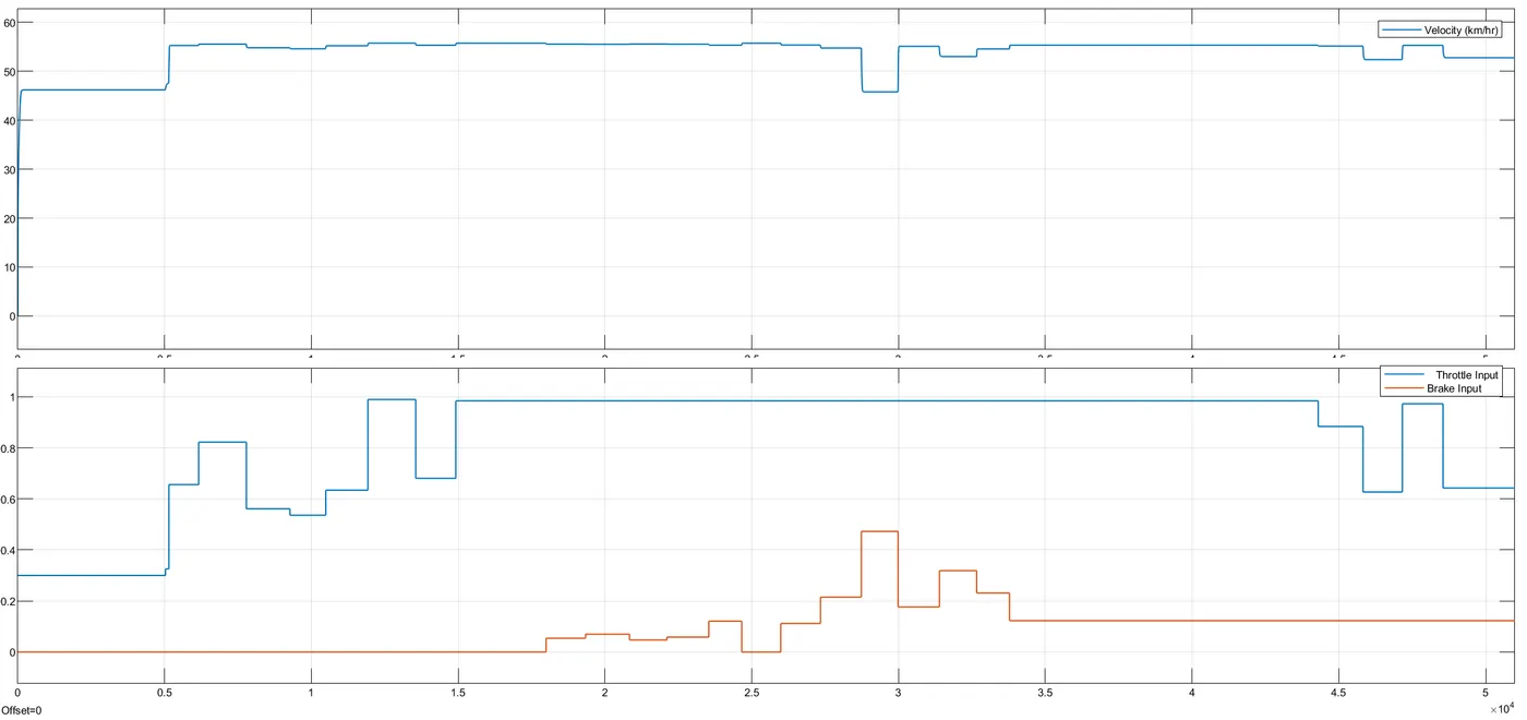
Velocity
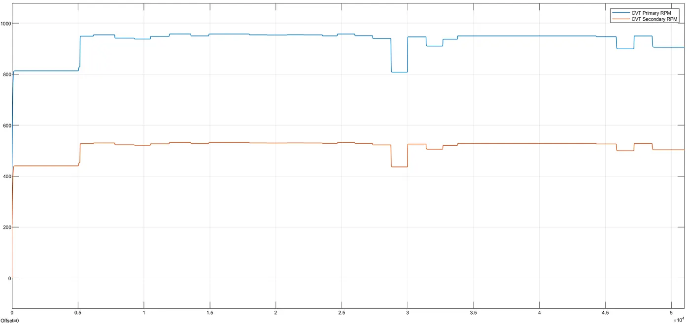
CVT Shaft Speed:
Engine Speed:
REFERENCES: