Project
AIM: To perform the Simulink Model on the Baja ATV vehicle model by changing the parameter like a break, and throttle and observing the variations.
Description:
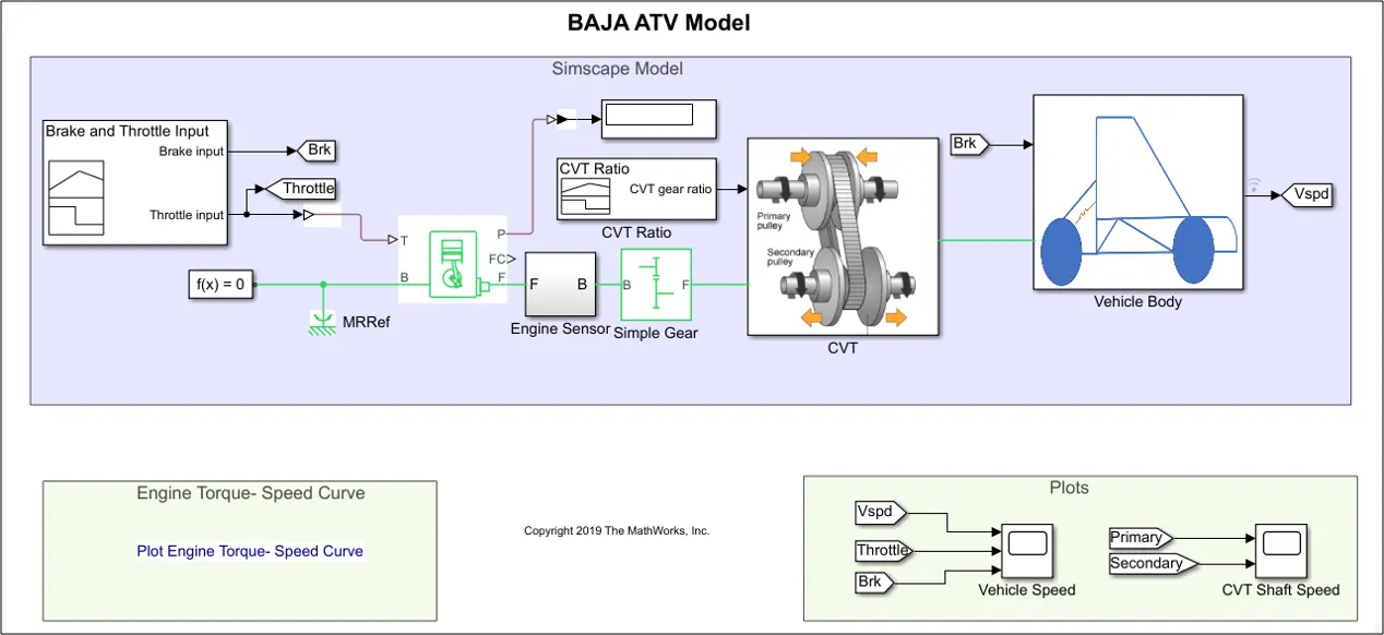
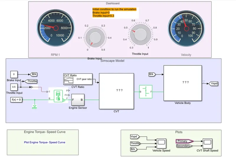
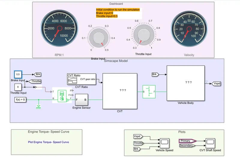
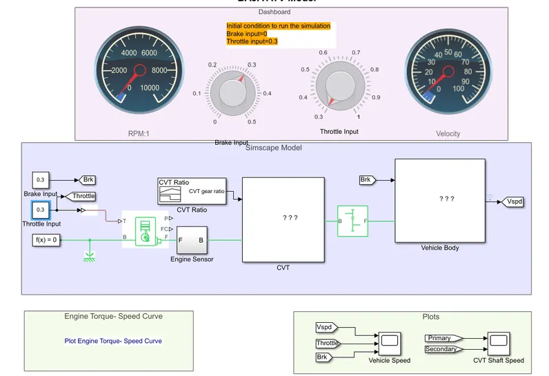
the components we are using in the above model are continuously variable transmission, vehicle body, generic engine, some fundamental components
The model of the continuously variable transmission
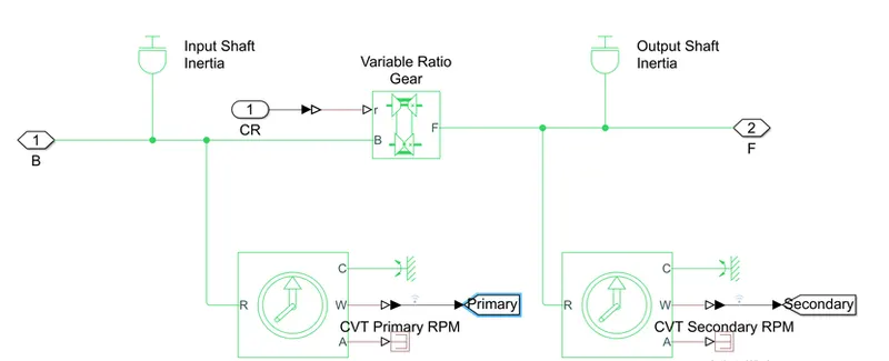
Simulink blocks used in the CVT
Variable ratio transmission: the variable transmission block represents a gearbox that dynamically transfers motion and torque between the two connected driveshaft axes, based and follower.
Inertia: the block represents an ideal mechanical rotational inertia used as the primary pully and secondary pully
Ideal rotational motion sensor: This block measures angular velocity or angle in a mechanical rotational network.
In CVT when the primary pully gets outwards then the secondary pully gets inward that time speed reduction happens. when primary pully gets in words then secondary pully gets outward that time speed overdrive happens.
firstly the condition Rs> Rp- Speed reduction
Secondly: condition Rp> Rs- overdrive
The secondary pulley is connected to the rare wheel
Vehicle body:
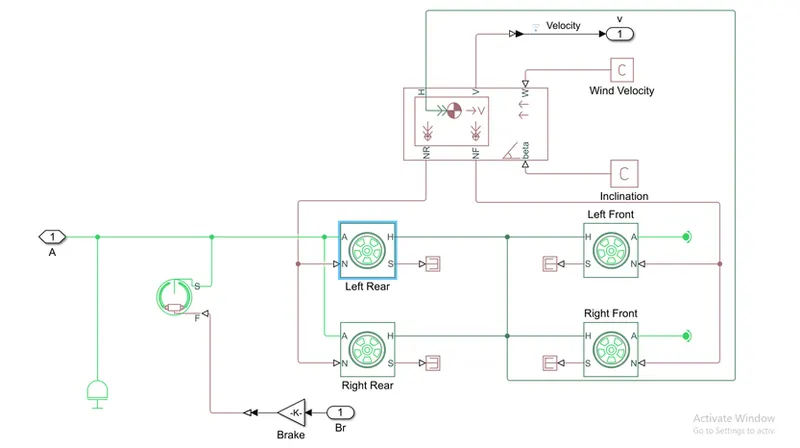
Block used in the vehicle body
Vehicle body: The vehicle body block represents a two-axle vehicle body in longitudinal motion.
Tire: The tire block models a tire with longitudinal behavior given by the magic formula an empirical equation based on four fitting coefficients.
Double shoe break: Represents a brake arranged as two pivoted rigid shoes symmetrically installed inside or outside a drum and operated by one actuator
generic engine:
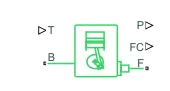 It represents a system level
Model of spark ignition and diesel engines suitable for use at initial stages of modeling when only the basic parameters are available optional idle speed and red line controllers are included.
To connect the CVT and engine we get a simple gear ratio
Dashboard
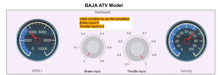
It is used for indications of speed rpm breek input, throttle input.
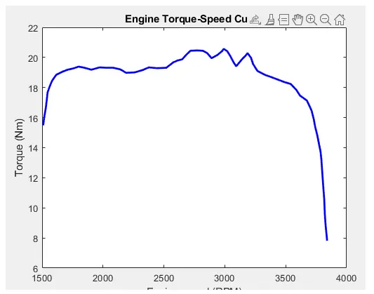
In this model used speed torque curve.
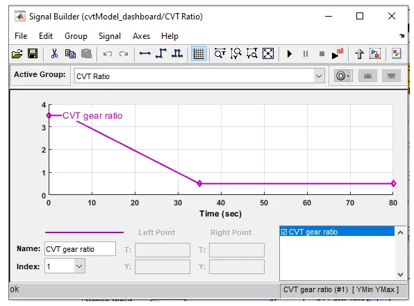
Signal bilder: it is used for to set ratio of CVT gear
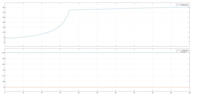
As per in aim we changed the parameters like break and throttle and we get following
the simulation is run for 100sec
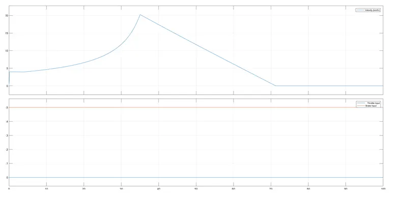
Max speed
| Throttle | break | max speed (t=100km/h) |
| 0.3 | 0 | 35 |
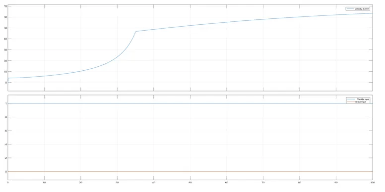
| 1 | 0 | 63 |
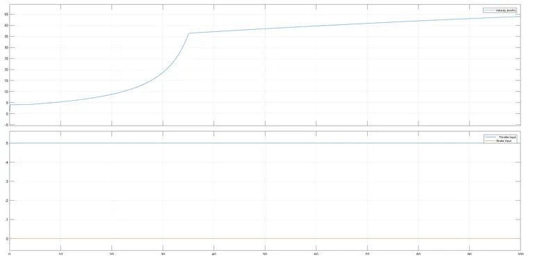
| 0.5 | 0 | 44 |
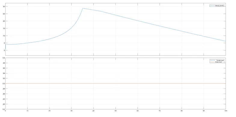
| 0.3 | 0.3 | 6.2 |
| 0 | 0.3 | 0 |
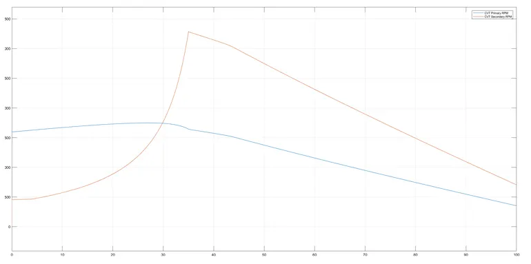
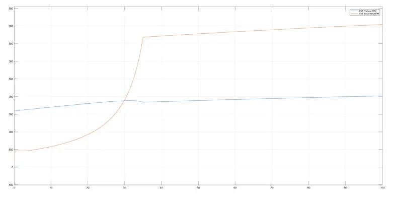
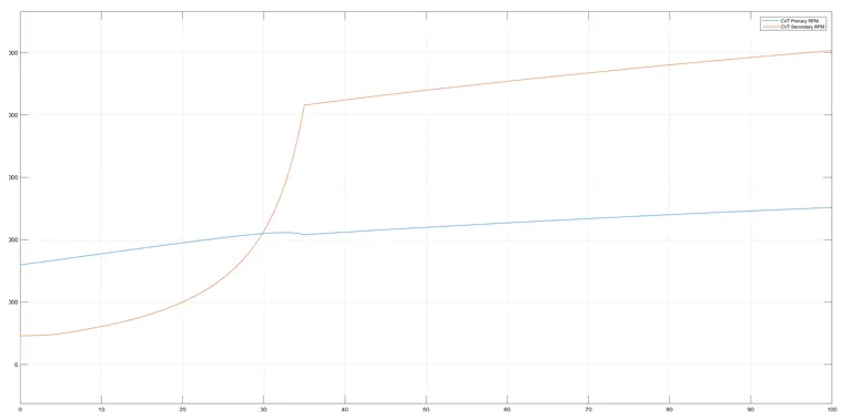
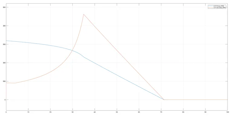
Shaft speed:
| Throttle | break | prime shaft speed | secondary shaft speed |
| 0.3 | 0 | 2024 | 4045 |
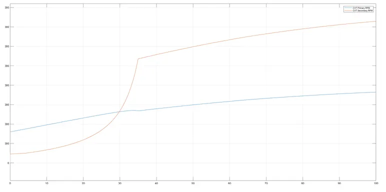
| 1 | 0 | 3643 | 7290 |
| 0.5 | 0 | 2515 | 5500 |
| 0.3 | 0.3 | 352.2 | 705 |
| 0 | 0.3 | 0 | 0 |
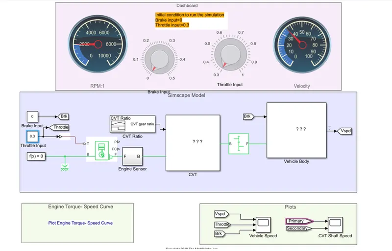
Model with throttle =0.3, break=0
Speed curve
Shaft speed curve
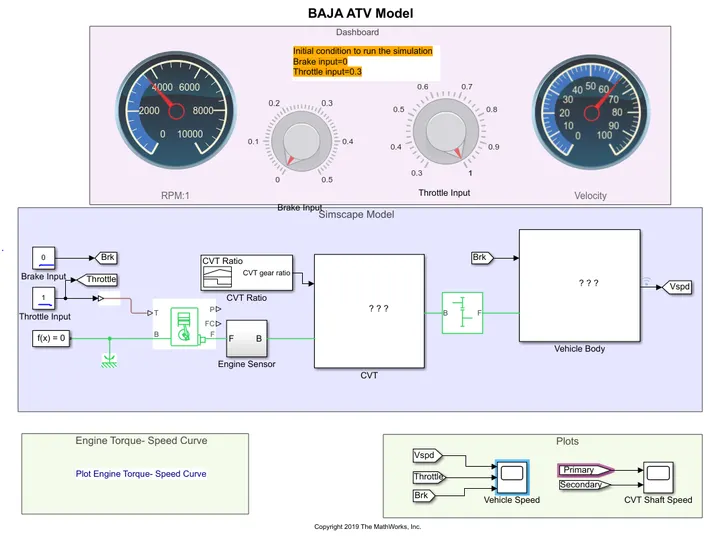
Model with throttle= 1, break=0
Speed curve
Shaft curve
Model with throttle =0.5, break=0
Speed curve
Shaft speed
Model with throttle =0, break=0.5
speed curve
shaft curve
Model with throttle =0.3, break=0.3
Speed curve
Shaft speed