Project
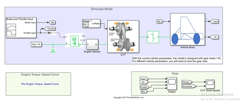
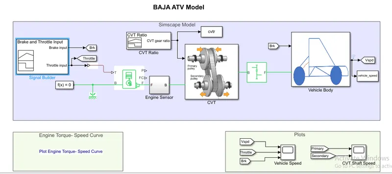
Studying the given CVT model:
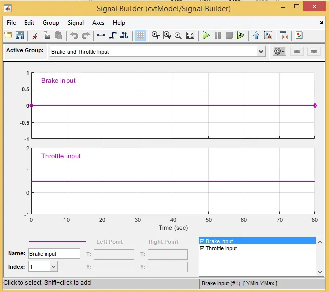
Brake and throttle input is defined using thesignal builder block:
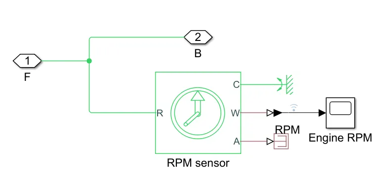
then we have generic engine block whose output is connected to the engine sensor block.
the engine sensor block is defined as follows:
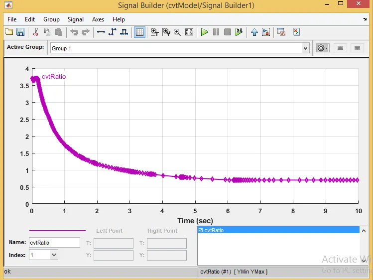
CVT gear ratio is defined as follows:
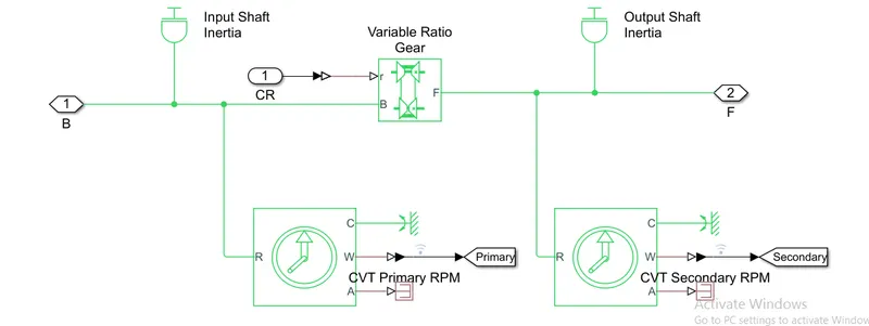
CVT block is defined as follows:
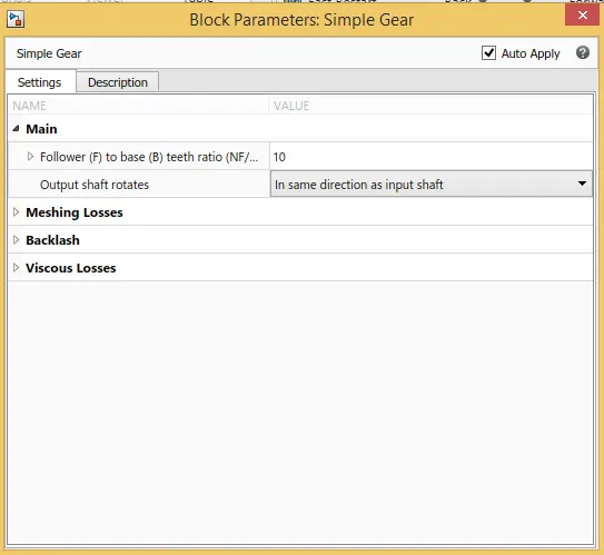
then we have a simple gear with gear ratio 10:
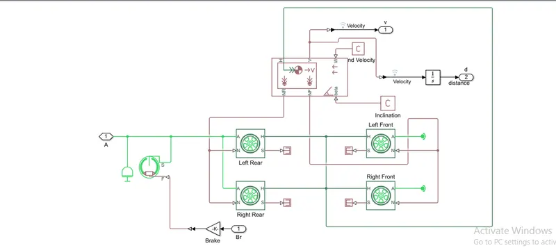
the vehicle body comprises of following blocks:
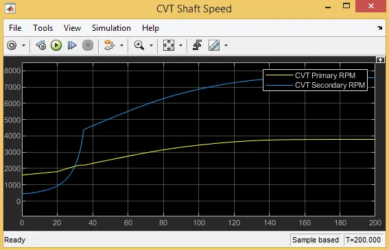
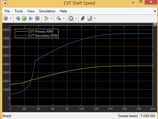
vehicle speed, distance, throttle input, the brake is displayed using a single scope and CVT primary shaft rpm and secondary shaft rpm are displayed using another scope.
Results:
case-1:Atv model With inputs given using signal builder block:
Model:
Throttle input and brake input:
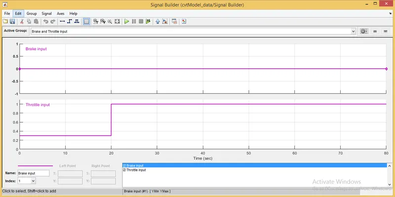
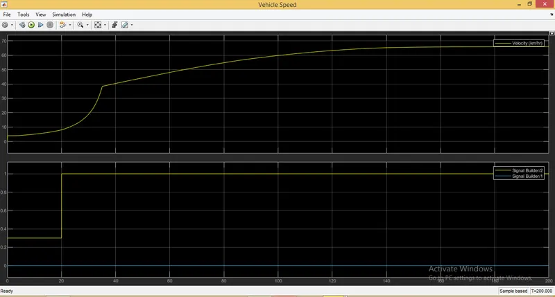
As we can see brake is not applied through out the time period and throttle is 0.3 from 0-20 sec and 1 from 20-80 sec.
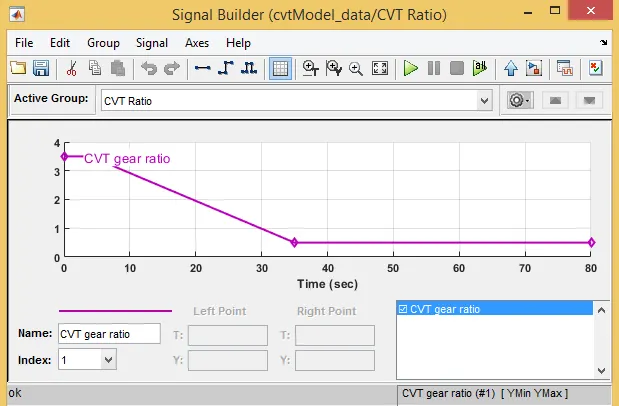
Cvt gear ratio variation with time:
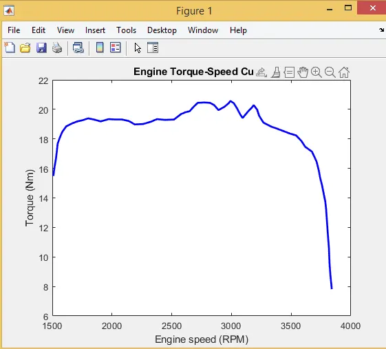
Engine torque speed curve:
Plot of vehicle speed, throttle and brake input:
Plot of cvt shaft speed primary and secondary:
case-2:Atv model With Dashboard:
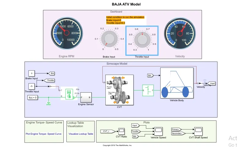
Model:
Throttle input and brake input:
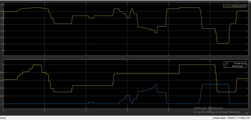
here we manually change the throttle and brake input during the simulation.
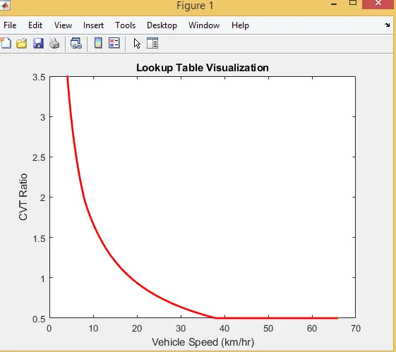
Cvt lookup table:
CVT ratio:
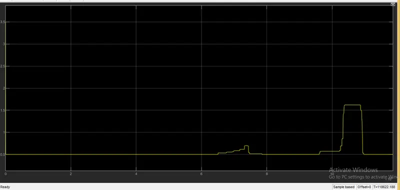
Plot of vehicle speed, throttle and brake input:
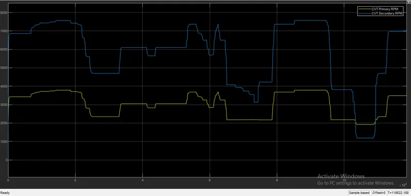
Plot of cvt shaft speed primary and secondary:
case-3:Atv model With look table:
Model:
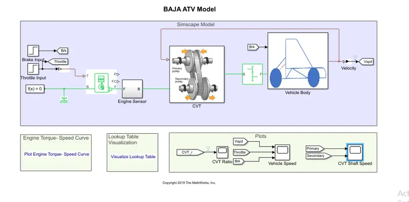
Lookup table visualisation:
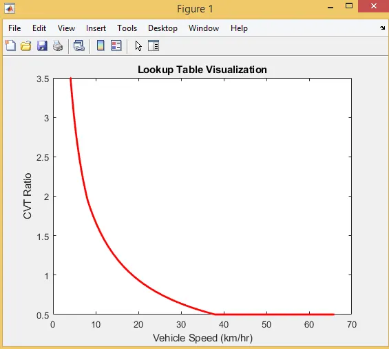
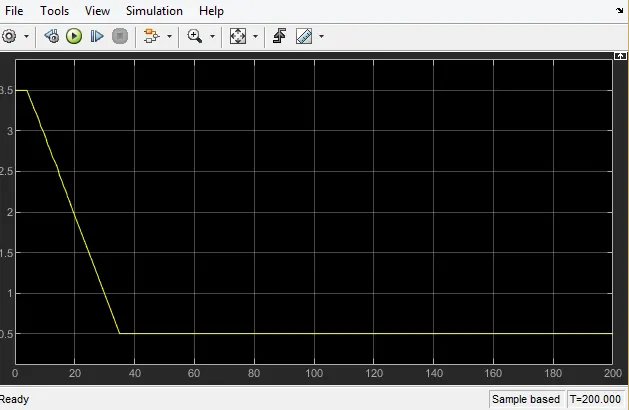
CVT Ratio:
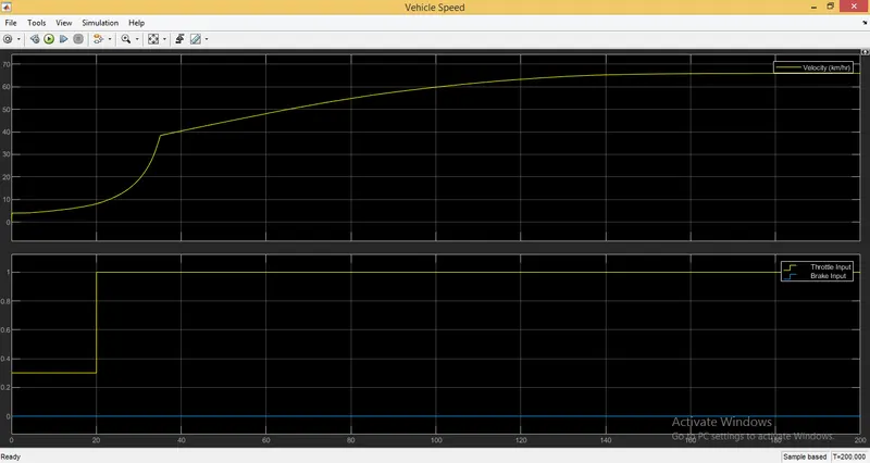
Plot of vehicle speed throttle input and brake applied with respect to time:
plot of cvt primary and secondary shaft speed.