Project
Objective
- To carry out a system level simulation of BAJA All-Terrain Vehicle which is available in the Mathworks portal and prepare a technical report explaining the model properties and commenting on result
Simulink model of All terrain vehicle
Introduction
- An all-terrain vehicle (ATV) is defined as a motorized off-highway vehicle designed to travel on four low-pressure or non-pneumatic tires, having a seat designed to be straddled by the operator and handlebars for steering control
- ATVs are subdivided into two types as designated by the manufacturer
- Type I ATVs are intended by the manufacturer for use by a single operator and no passenger
- Type II ATVs are intended by the manufacturer for use by an operator and a passenger, and are equipped with a designated seating position behind the operator
- Similarly, riders must also consider the various ATV sizes
- ATVs are not “one size fits all.” The ATV industry recommends all riders operate an ATV intended for their age
- Youth model ATVs are designed for smaller hands and feet, and travel at slower speeds appropriate for their age
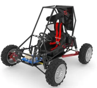
Continuosly variable transmission (CVT)
- A CVT transmission, or continuously variable transmission, seamlessly changes through an unending range of effective gear ratios while you drive, whereas other kinds of mechanical transmissions offer a fixed number of gear ratios and have hard shifts between each
- CVT transmission systems are also known as single-speed, shiftless, and stepless transmissions.
- The shiftless nature of a CVT offers unparalleled flexibility that maintains constant angular velocity regardless of output speed. Additionally, a CVT makes accelerating smooth and offers enhanced fuel economy.
Simscape Model
BAJA ALL-Terrain Vehicle Simscape model without lookup table
Without Dashboard
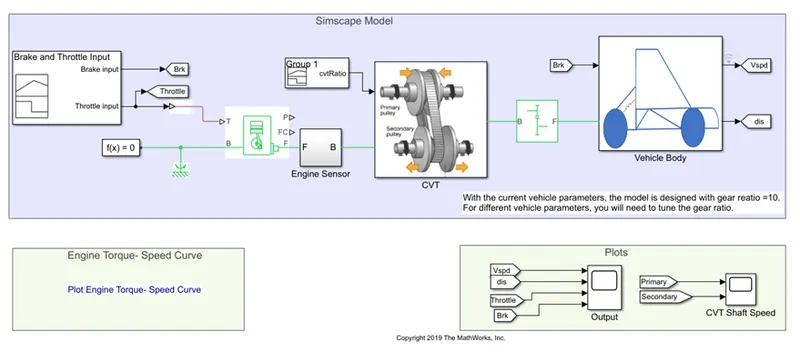
- The following are the subsystem and blocks used in the given model
- Generic Engine
- The Generic Engineblock represents a general internal combustion engine
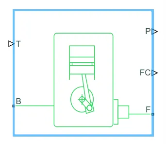
- This block is a suitable generic engine for spark-ignition and diesel
- Speed-power and speed-torque parameterizations are provided
- A throttle physical signal input specifies the normalized engine torque
- Optional dynamic parameters include crankshaft inertia and response time lag
- A physical signal port outputs the engine fuel consumption rate based on the fuel consumption
- Optional speed and redline controllers prevent engine stall and enable cruise control
- Connections F and B are mechanical rotational conserving ports associated with the engine crankshaft and engine block, respectively
- Connections P and FC are physical signal output ports through which engine power and fuel consumption rate are reported
- Connection T is physical signal of throttle input to the engine
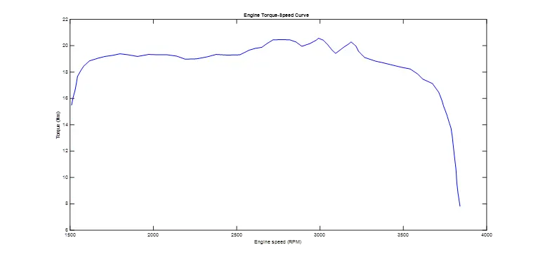
- The above plot represents the engine torque -speed curve
- Engine parameterization:
- Model parameterization – Tabulated torque data
- Engine inertia – 0.008kg/m2
- Initial Velocity – 1750 rpm
- Limits – Speed Threshold – 100 rpm
- Fuel consumption and speed limit – No fuel consumption and speed limit off
- Engine Sensor
- This subsystem used to measure the engine speed as engine speed sensor
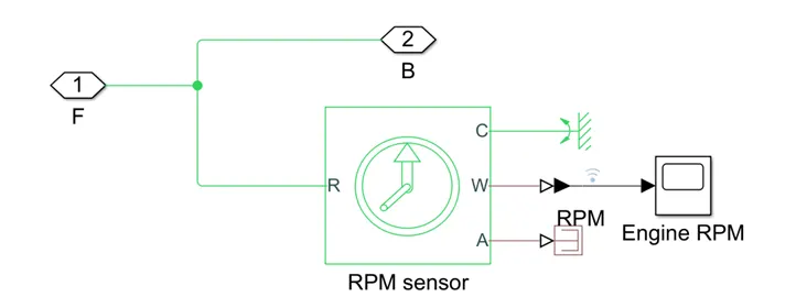
- Ideal Rotational Motion senor block is used to measure the Engine rpm in between the CVT and the Engine
- This block measures angular velocity or angle in a mechanical rotational network
- The sensor is ideal since it does not account for inertia, friction, delays, energy consumption, and so on
- The physical signal ports W and A report the angular velocity and angle, respectively, of port R relative to port C
- The measured angular velocity is positive when the angular velocity at port R is greater than the angular velocity at port C
- Continuously Variable Transmission
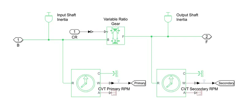
- This subsystem is used to transmit the power from the engine to the vehicle body through simple gear
- The following are the block used in this subsystem
- Variable Ratio Transmission - Represents a variable ratio gearbox such as implemented by mechanical belt CVT, electric, or hydraulic transmissions
- The physical signal input r defines the ratio of input to output angular shaft velocities
- Connections B (base) and F (follower) are mechanical rotational conserving ports
- Specify the relation between base and follower rotation directions with the Output shaft rotates parameter
- Configured as the output shaft rotates in the same direction as input shaft
- Ideal Rotational Inertia - The block has one or two mechanical rotational conserving ports
- The difference is purely graphical, as the ports are rigidly linked
- The block positive direction is from its port to the reference point
- This means that the inertia torque is positive if the inertia is accelerated in the positive direction
- Input shaft Inertia – 3.5*(((18.6e-2)/2)2+((2.5e-2)/2)2)/2 kg*m2
- Output shaft inertia – 3.2*(((19.8e-2)/2)2+((1.9e-2)/2)2)/2 kg*m2
- Ideal rotational Motion sensor – Two sensors are used to measure the input and the output shaft speed in rpm
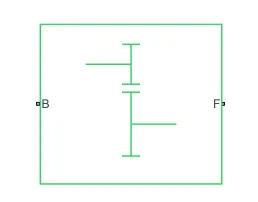
- Simple Gear
-
-
- This block is connected in between the CVT and the axles as a constant gear of differential gear transmission to transmit the power from CVT to vehicle wheel
-
- Generic Engine
-
-
- This block represents a fixed-ratio gear or gear box. No inertia or compliance is modelled in this block
- Connections B (base) and F (follower) are mechanical rotational conserving ports
- Specify the relation between base and follower rotation directions with the Output shaft rotates parameter
- Optionally include thermal effects and expose thermal conserving port H by setting Friction model to a temperature-dependent setting
- Constant gear ratio – 10:1
-
-
- Vehicle Body
- This subsystem is used to add the vehicle body effects due to air drag, tire resistance, mass of the body, gradeability effect to the model
- Vehicle body - Represents a two-axle vehicle body in longitudinal motion
- The block accounts for body mass, aerodynamic drag, road incline, and weight distribution between axles due to acceleration and road profile
- The vehicle can have the same or a different number of wheels on each axle

Optionally include pitch and suspension dynamics or additional variable mass and inertia- The vehicle does not move vertically relative to the ground
- Connection H is the mechanical translational conserving port associated with the horizontal motion of the vehicle body
- The resulting traction motion developed by tires should be connected to this port
- Connections V, NF, and NR are physical signal output ports for vehicle velocity and front and rear normal wheel forces, respectively
- Wheel forces are considered positive if acting downwards. Connections W and beta are physical signal input ports corresponding to headwind speed and road inclination angle, respectively
- If variable mass is modelled, the physical signal input ports CG and M are exposed. CG accepts a two- element vector representing the x and y distance offsets from vehicle CG to additional load mass CG
- M represents the additional mass
- If both variable mass and pitch dynamics are included, the physical signal port J accepts the inertia of the additional mass about its own CG
- Vehicle body parameterization:
- Mass – 250 kg
- No of axles – 2
- Horizontal distance from CG to front axle – 1m
- Horizontal distance from CG to rear axle – 0.35m
- CG height above ground – 0.7m
- Gravitational acceleration – 9.81 m/s2
- Frontal Area – 0.735482 m2
- Drag Coefficient – 1.92
- Air density – 1.18 kg/m3
- Tire - Represents the longitudinal behaviour of a highway tire characterized by the tire Magic Formula
- The block is built from Tire-Road Interaction (Magic Formula) and Simscape Foundation Library Wheel and Axle blocks
- Optionally, the effects of tire inertia, stiffness, and damping can be included
- Connection A is the mechanical rotational conserving port for the wheel axle
- Connection H is the mechanical translational conserving port for the wheel hub through which the thrust developed by the tire is applied to the vehicle
- Connection N is a physical signal input port that applies the normal force acting on the tire
- The force is considered positive if it acts downwards
- Connection S is a physical signal output port that reports the tire slip
- Optionally expose physical signal port M by setting Parameterize by to Physical signal Magic Formula coefficients
- Physical signal port M accepts a four-element vector corresponding to the B, C, D, and E Magic Formula coefficients
- Tire parameterization:
- Parameterize by - Peak longitudinal force and corresponding slip
- Rated vertical load – 2060 N
- Peak longitudinal force at rated load – 1260 N
- Slip at peak force at rated load (percent) – 5
- Rolling radius – 0.2921 m
- Tire inertia – 1e-2 kg*m2
- Rolling resistance – on
- Resistance model – Constant coefficient
- Constant coefficient – 0.015
- Velocity threshold – o.1 m/s
- Double shoe brake - Represents a brake arranged as two pivoted rigid shoes symmetrically installed inside or outside a drum and operated by one actuator
- The actuator force causes the shoes to exert a friction torque on a shaft connected to the drum
- Connection S is a conserving rotational terminal associated with the drum shaft
- Connection F is a physical signal port representing the force input to the actuator
- Positive force creates friction torque that resists shaft rotation
- Optionally include thermal effects and expose thermal conserving port H by setting Thermal port to Model
- Dual shoe brake parameterization:
- Drum radius – 150 mm
- Actuator location radius – 100 mm
- Pin location radius – 125 mm
- Pin location angle – 15 deg
- Shoe beginning angle – 5 deg
- Shoe span angle – 120 deg
- Viscous friction coefficient – 0.01 N*m/(rad/s)
- Contact friction coefficient – 0.3
- Angular velocity threshold – 0.01 rad/s
- Constant –This used to provide the inclination and wind velocity input to the vehicle body
- Integrator – it is used to calculate the distance using the angular velocity
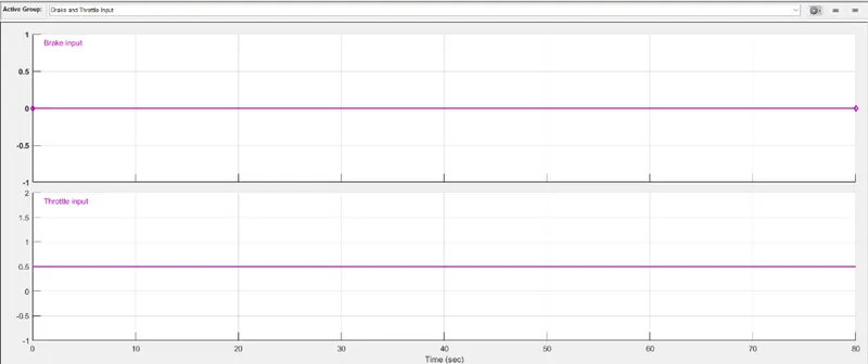
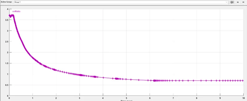
Signal Builder - This block is used to generate the throttling and braking input to the engine and the one more block is used to generate the CVT transmission ratio. The constant throttling effect is provided without applying the brake- Solver configuration – Defines the solver setting to the user configuration
- Scope – To plot the simulation results
- Vehicle Body
With dashboard
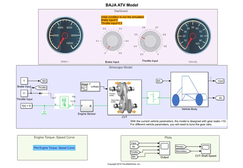
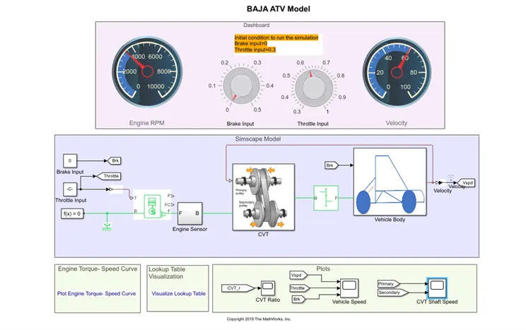
- The model which is explained above for without dashboard model is used to build a model with dashboard. Instead of using signal builder block for providing throttling and braking effect, the adjustable knob is used to adjust the throttling and braking and Dial gauge is used to monitor the given effect
Simulation results
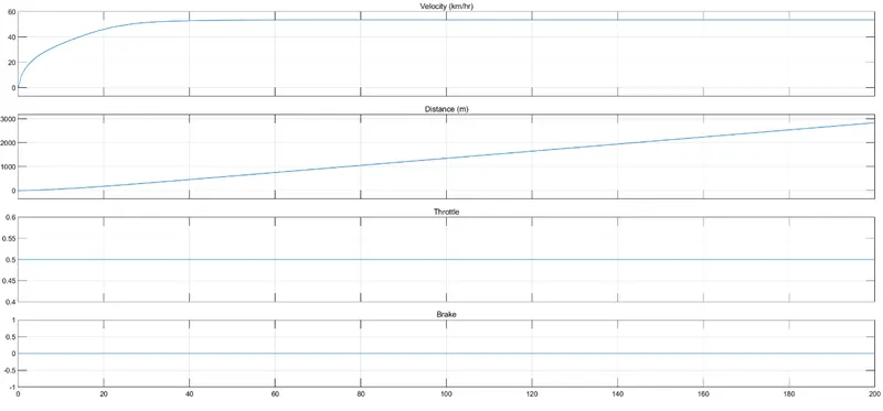
- The above graph represents the velocity and distance covered by the system with respect to the given throttling input of constant speed request and no braking apply condition
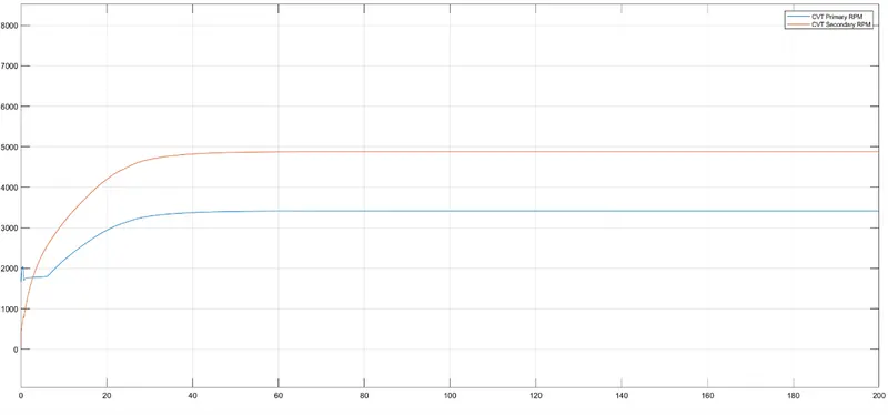
The above shown represents the working of the CVT with respect to the variable gear ratio input given to the system by running the engine at constant speed- Since the engine is running at the constant speed due to constant throttling input, the required wheel end torque to move the vehicle initially and the constant speed of the vehicle is also maintained by the effect of the continuously variable transmission system
BAJA ALL-Terrain Vehicle Simscape model with lookup table
With Dashboard
The model developed for without lookup table model with dashboard is used expect the signal builder to vary the CVT gear ratio
- Instead of signal builder block. Lookup table is used to provide the input to the CVT to change the gear ration with respect to the velocity (Vehicle speed)
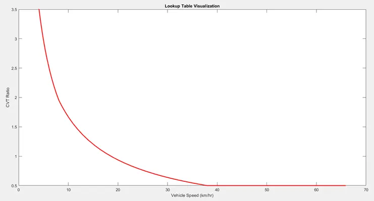
- The above graph represents the CVT ration with respect to the Vehicle speed. The speed is greater than the 38 kmph the gear ration is maintained as least gear ration to main the speed of the vehicle
Inference
- The velocity of the vehicle, engine speed are directly proportional to the throttling input and inversely proportional to the braking input
- CVT ration is directly proportional to the torque and inversely proportional to the throttle input
- CVT secondary shaft is greater than the primary shaft since the CVT ration is directly proportion to the shaft diameter
Reference
- BAJA ATV Model file