Project
PROJECT 1
AIM :
To study and analyze the BAJA All Terrain Vehicle (ATV) model using Simulink and compare between different models.
OBJECTIVES :
- To Prepare a technical report explaining the functions of the subsystems & blocks used for preparing the model
- To Explain in detail all the differences between all the five models provided
- To undertand and comment on the results
Introduction:
All Terrain Vehicle:
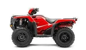
An all-terrain vehicle (ATV) is defined as a motorized off-highway vehicle designed to travel on four low-pressure or non-pneumatic tires, having a seat designed to be straddled by the operator and handlebars for steering control. ATVs are subdivided into two types as designated by the manufacturer. Type IATVs are intended by the manufacturer for use by a single operator and no passenger. Type II ATVs are intended by the manufacturer for use by an operator anda passenger, and are equipped with a designated seating position behind the operator.
Continuously Variable Transmission(CVT):
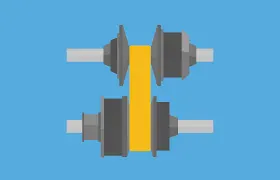
A continuously variable transmission (CVT) is anautomatic transmssion that can change seamlessly through a continuous range of gear ratios. This contrasts with other transmissions that provide a limited number of gear ratios in fixed steps. The flexibility of a CVT with suitable control may allow the engine to operate at a constant RPM while the vehicle moves at varying speeds.
Main and critical blocks used:
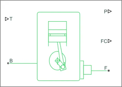
Generic Engine block:
Main ports:
- B – Rotational Conserving Port :representing the Engine Block(should be connected to rotational motion reference)
- F – Rotational Conserving Port :representing the Engine Crankshaft
- T - Physical signal input port :specifying the normalized engine throttle level
- P - Physical signal output port: reporting the instantaneous engine power, in W
- FC - Physical signal output port: reporting the fuel consumption rate, in kg/s
Simple Gear:
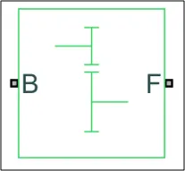
The follower-base gear ratio is
gFB = rf/rb = NF/NB
where:
NB is the number of teeth in the base gear
NBF is the number of teeth in the follower gear
Main Ports:
B — Base: Rotational mechanical conserving port associated with the base, or input, shaft.
F Follower: Rotational mechanical conserving port associated with the follower or output shaft
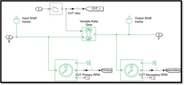
Variable Ratio Transmission block:
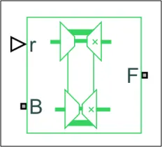
Main ports:
- B – Base Pulley or Drive Pulley
- F – Follower Pulley or Driven Pulley
- r – Variable Transmission Ratio (Input)
Vehicle Body block:
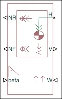
Input ports:
- Beta – Road Incline Angle (rad):physical signal input port for road incline angle
- W – Head Wind Speed (m/s):physical signal input port for road incline angle
- CG-center of gravity(m):physical signal input port of externally defined mass relative to the cg of vehicle(only available with externally defined additional mass is set to on)
- M-mass(kg):physical signal input port for mass of the externally defined mass(only available with externally defined additional mass is set to on)
- J-Externally defined moment of inertia(in kg*m^2):physical signal input port of the externally defined mass
Output ports:
- NR – Rear Axle Normal Force (N): physical signal output port for the rear axle which is considered positive acting downward
- NF – Front Axle Normal Force (N):physical signal output port for the front axle which is considered positive acting downward
- V – Longitudinal Velocity (m/s):physical output signal of vehicle velocity
Conserving ports:
H – Horizontal Motion: conserving port related to the horizontal motion of vehicle body(tyres should be connected to this port)
Double shoe brake Block:
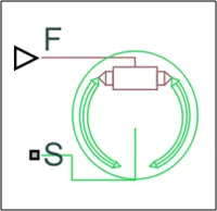
Input ports:
F - Physical signal input port associated with the applied actuating force
Conserving ports:
S - Rotational conserving port associated with the rotating drum shaft
Tire(magic formula) block:
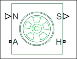
Other Blocks used:
1. Solver Configuration – To specify the solver parameters before starting the simulation2. Signal Builder – To input the Brake, Throttle and CVT Ratio
3. Simulink to PS Converter – To convert the Simulink signal to Simscape environment
4. PS to Simulink Converter – To convert Simscape signal to Simulink environment
5. Mechanical Reference – To make sure all the components are clamped to the ground
6. Rotational free end: The Rotational Free End block represents a mechanical rotational port that rotates freely, without torque.
7. Scope – To display different graphs
8. Display – To view the calculated engine power
9. Inertia – To represent the solid inertia
10. Rotational Motion Sensor – To sense the rotational motion from the engine and give output as rpm
11. PS Terminator - Terminator for unconnected physical signal outputs
12. PS Constant - Generate constant physical signal
13. Rotational Free End – For mechanical component (Tire)
14. Custom Measure Gauge – To measure the brake and throttle input
15. Knob – To increase, decrease and vice-versa of throttle and brake inputs
16. Lookup Table – To insert the CVT values from the workspace
17. Step – To increase or decrease an input value for a defined time interval
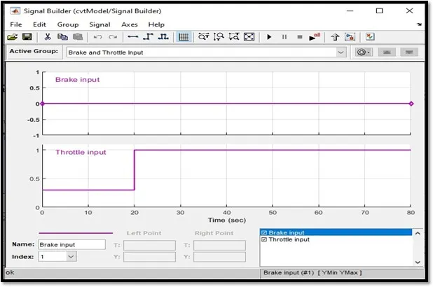
INPUT SIGNAL:
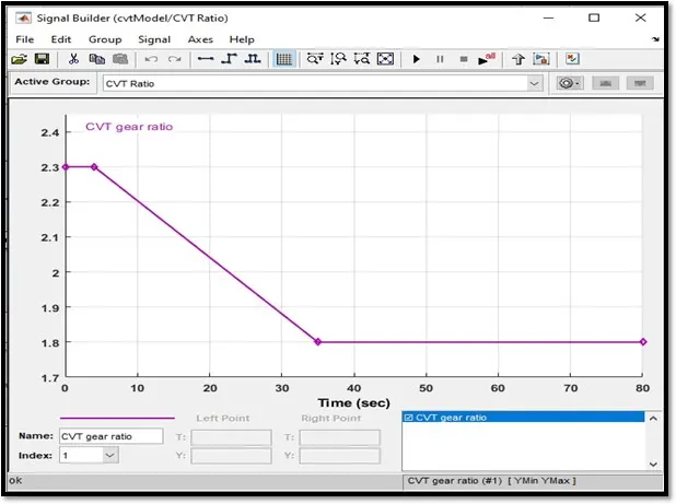
CVT Gear Ratio Input:
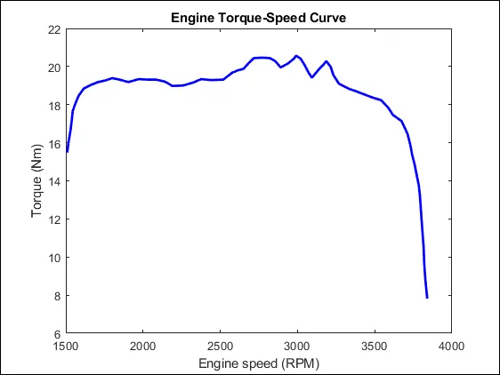
Torque vs Engine Speed input:
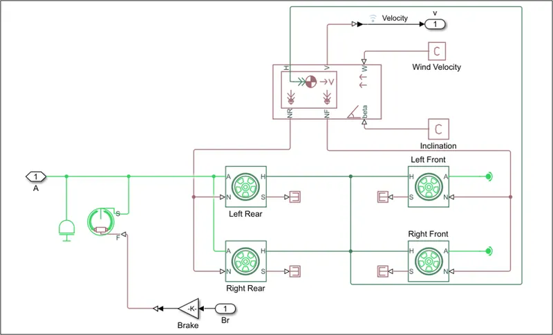
VEHICLE BODY:
OUTPUT:
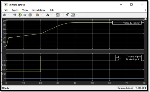
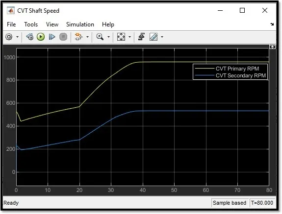
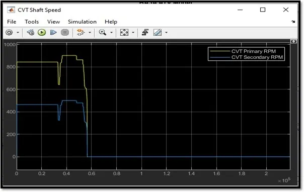
CASE1:
SIMULINK MODEL FOR BAJA ATV WITH CVT USING DASHBOARD:
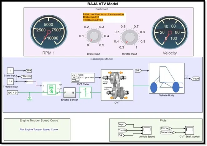
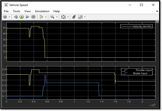
CASE 2:
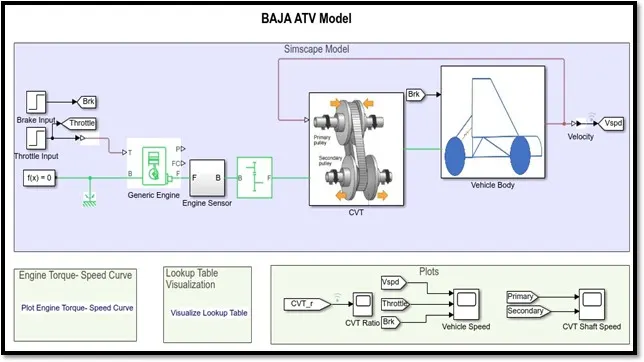
SIMULINK MODEL FOR BAJA ATV WITH CVT USING LOOKUP TABLE:
CASE 3:
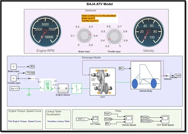
SIMULINK MODEL FOR BAJA ATV WITH CVT USING LOOKUP TABLE & DASHBOARD:
CONCLUSION:
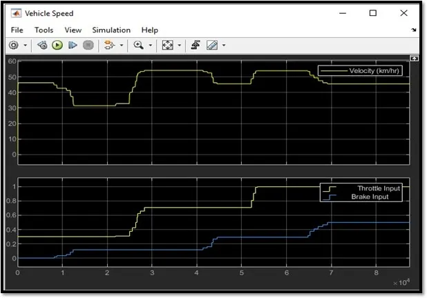
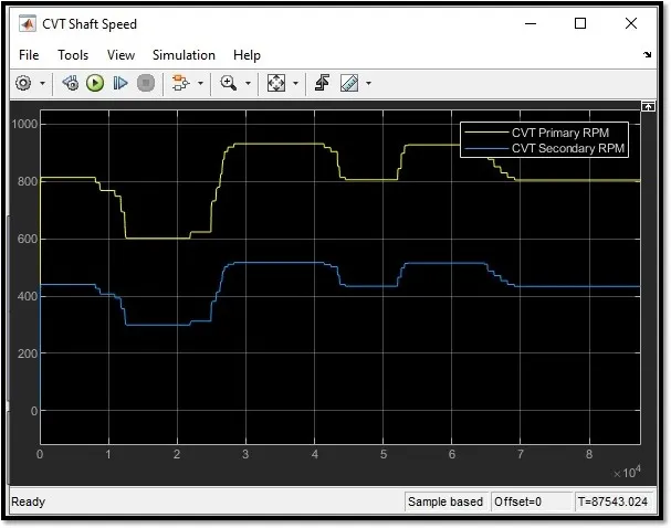
Thus we have successfully analysed 4 different models of BAJA ATV WITH CVT and recorded the outputs: - (Vehicle velocity & CVT shaft rpm) with respect to variations in input throttle and brake.
Reference:
https://www.mathworks.com/matlabcentral/fileexchange/70576-baja-all-terrain-vehicle-atv-model