Project
#Aim:
To perform the simulation of BAJA All-Terrain vehicle model and observe the vehicle speed and CVT shaft speed output graph by changing break and throttle inputs.
Theory:
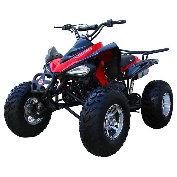
An all-terrain vehicle (ATV), also known as a quad (cycle), three-wheeler, four-track, four-wheeler, or quadricycle, as defined by the American National Standards Institute (ANSI) is a vehicle that travels on low-pressure tires, with a seat that is straddled by the operator. along with handlebars for steering control. As the name implies, it is designed to handle a wider variety of terrain than most other vehicles.
By the current ANSI definition, ATVS are intended for use by a single operator, although some companies have developed ATVs intended for use by the operator and one passenger. These ATVs are referred to as tandem ATVs.
The rider sits on and operates these vehicles like a motorcycle, but the extra wheels give more stability at slower speeds. Although most are equipped with three or four wheels, six-wheel models exist for specialized applications.
Major and Crucial Components:
1.CVT
2.Vehicle Body
3.Generic Engine
4.Simple Gear
5.Tires and Brakes
1.CVT-
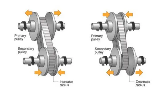
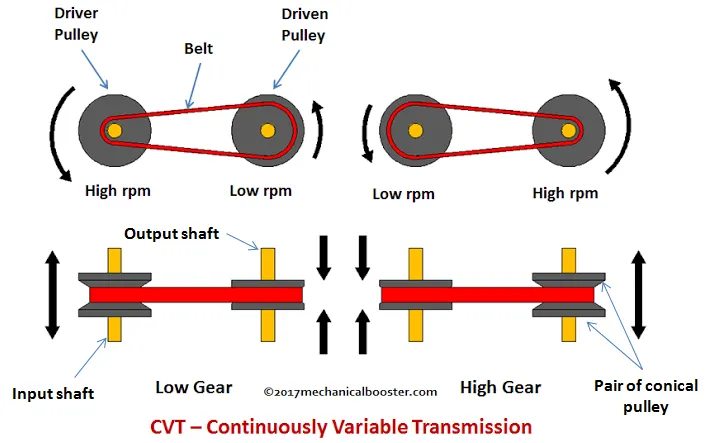
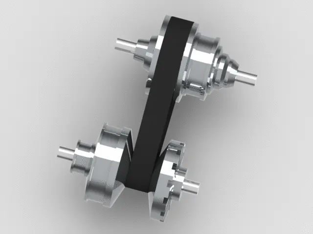
A continuously variable transmission (CVT) is an automatic transmission that can change seamlessly through a continuous range of gear ratios.This contrasts with other transmissions that provide a limited number of gear ratios in fixed steps. The flexibility of a CVT with suitable control may allow the engine to operate at a constant RPM while the vehicle moves at varying speeds.
CVTs are used in automobiles, tractors, motor scooters, snowmobiles, bicycles and earthmoving equipment. Its compact size and simplicity of construction mean it's more cost-effective to use in a small car than a conventional automatic gearbox.
A CVT is an automatic, single-speed, and gearless transmission that can shift through an infinite number of gear ratios. A continuously variable transmission (CVT) is a transmission that operates on an ingenious pulley system that automatically varies the transmission ratio, allowing an infinite variability (theoretically) between highest and lowest gears with no discrete steps or shifts. CVTs provide more useable power, better fuel economy, and a smoother driving experience than traditional transmissions that use gearboxes with fixed numbers of gear sets. It has a relatively simple arrangement of two cone-shaped pulleys with a V-shaped drive belt connecting them. One pulley is attached to the engine, while the other is joined to the wheels. When you press the accelerator, the engine revs and the cone moves according to the amount of power asked for. The other cone adjusts accordingly so that the drive belt mainkans the same tension, and this is what determines how the car accelerates.
CVT Subsystem-
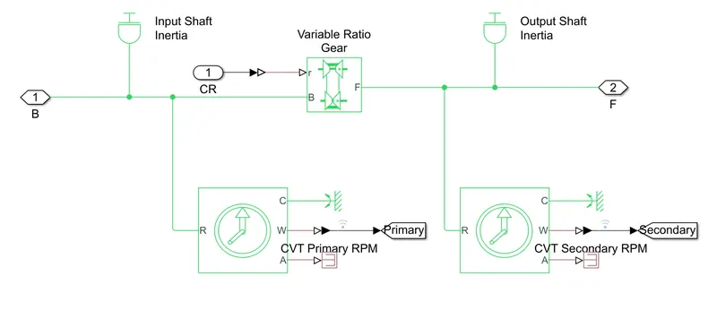
- The CVT subsystem uses a Variable Gear Ratio block-
- Inside the CVT subsystem, 2 Inertia blocks are connected to ensure proper inertial motion.
- Two Ideal Rotational Motion Sensors are connected, one on either side of the Variable Gear Ratio. The angular velocity outputs of these are then transferred to the main model with the help of GoTo blocks
i)Variable Ratio Gear:
The ratio of the follower to base angular speed decreases with gear ratio, and conversely the ratio of the follower to base torque increases with gear ratio. The variable gear is implemented using the Variable Ratio Transmission block which includes compliance
The variable gear arrangements of CVT in this model is represented by the Variable Ratio Gear Block:
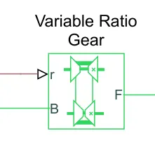
Where.
- B-Base Pulley or Drive Pulley.
- F-Follower Pulley or Driven Pulley
- r-Variable Transmission Ratio (Input).
ii)Ideal Rotational Motion sensor-
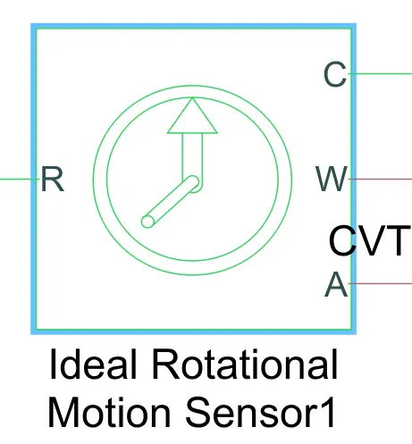
Where,
- R- Rod(positive prob)
- C- Case (reference probe)
- W- Angular velocity, rad/s
- A- Angular displacement, rad
The block represents an ideal mechanical rotational motion sensor, that is, a device that converts an across variable measured between two mechanical rotational nodes into a control signal proportional to angular velocity or angle. The sensor is ideal since it does not account for inertia, friction, delays, energy consumption, and so on. Connections R and C are mechanical rotational conserving ports and connections W and A are physical signal output ports for velocity and angular displacement, respectively.
2.Vehicle body-
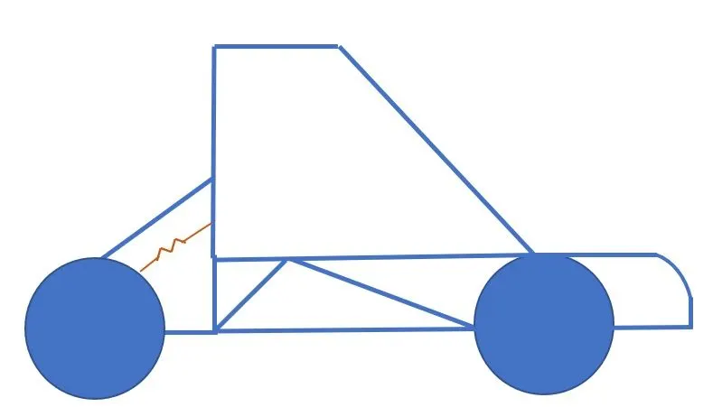
A Baja ATV of a Two-axle type vehicle with longitudinal dynamics and motion: has adjustable mass, geometry and drag properties. The vehicle may have the same or a different number of wheels on each axle. For example, two wheels on the front axle and one wheel on the rear axle. The vehicle wheels are assumed identical in size. The vehicle can also have a center of gravity (CG) that is at or below the plane of travel so that it mitigates the chances of rolling over
Vehicle Subsystem-
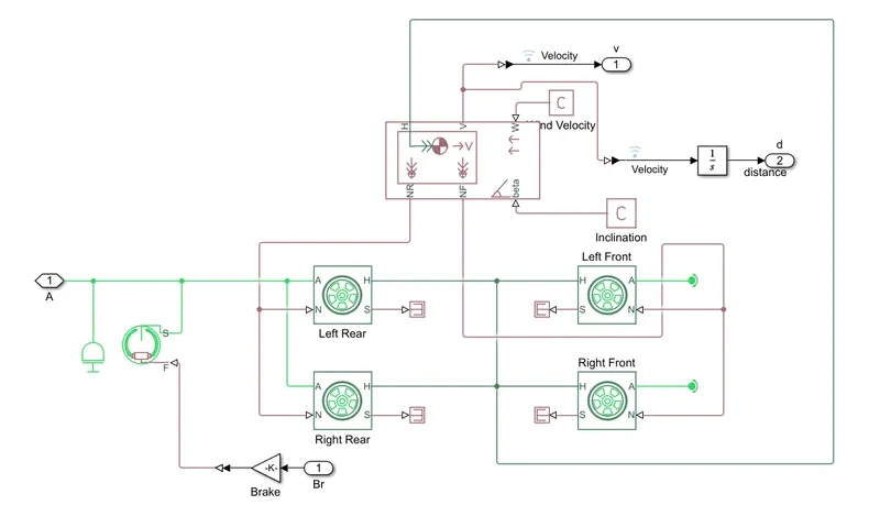
Vehile Boody-
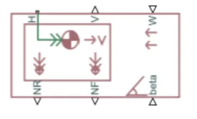
Where,
- H- Horizontal motion
- V- Longitudinal velocity, m/s
- W- Headwind speed, m/s
- beta- Road incline angle, m/s scaler
- NF- Front axle normal force,N scalar
- NR- Rear axle normal force, N
The Vehicle Body block represents a two-axle vehicle body in longitudinal motion. The vehicle can have the same or a different number of wheels on each axle. For example, two wheels on the front axle and one wheel on the rear axle. The vehicle wheels are assumed identical in size. The vehicle can also have a center of gravity (CG) that is at or below the plane of travel.
The block accounts for body mass, aerodynamic drag, road incline, and weight distribution between axles due to acceleration and road profile. Optionally include pitch and suspension dynamics. The vehicle does not move vertically relative to the ground.
The block has an option to include an externally-defined mass and an externally-defined inertia. The mass, inertia, and center of gravity of the vehicle body can vary over the course of simulation in response to system changes.
3.Generic Engine-
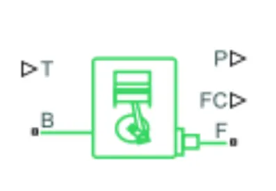
The Generic Engine block represents a general Internal Combustion (IC) Engine which is a type of Compression Ignition (CI-Diesel) or Spark Ignition (SI-Petrol). The speed torque and speed power parameters are provided by the designer.
Where.
- B-Rotational Conserving Port representing the Engine Block
- F-Rotational Conserving Port representing the Engine Crankshaft
- T-Physical signal input port specifying the normalized engine throttle level
- P- Physical signal output port reporting the instantaneous engine power, in W
- FC Physical signal output port reporting the fuel consumption rate, in kg/s
The Generic Engine block represents a general internal combustion engine. This block is a suitable generic engine for spark-ignition and diesel. Speed-power and speed-torque parameterizations are provided. A throttle physical signal input specifies the normalized engine torque. Optional dynamic parameters include crankshaft inertia and response time lag. A physical signal port outputs the engine fuel consumption rate based on the fuel consumption model that you choose. Optional speed and redline controllers prevent engine stall and enable cruise control.
4)Simple Gear:
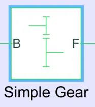
This block Represents a fixed-ratio gear or gear box. No inertia or compliance is modeled in this block. You can optionally include gear meshing and viscous bearing losses.
Connections B (base) and F (follower) are mechanical rotational conserving ports. Specify the relation between base and follower rotation directions with the Output shaft rotates parameter. Optionally include thermal effects and expose thermal conserving port H by right-clicking on the block and selecting Simscape block choices to switch between variants.
Simple Gear. The simple gear is a combination of a driver and driven gear where the speed is reduced by the gear ratio.
The gear ratio is defined as: Gear Ratio=FollowerGear Speed/BaseGear Speed
Where,
B-Base Gear or Driver Gear & F- Follower Gear or Driven Gear.
5) Tires and Brakes:
i)Tires-
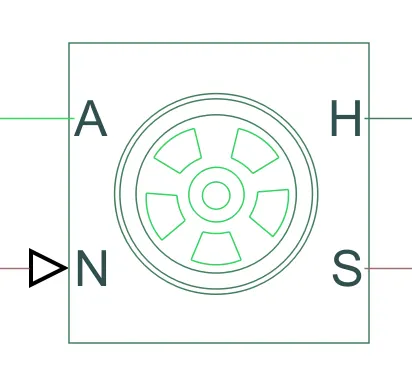
The vehicle body is connected to 4 tires each per axle to move the vehicle according to the power input to the axle.
Where,
- N- Normal Force
- S-Tire Slip
- A- Axle
- H-Mechanical translational port associated with the wheel hub that transmits then the thrust generated by the
tire to the remainder of the vehicle
ii)Double Shoe Brake-
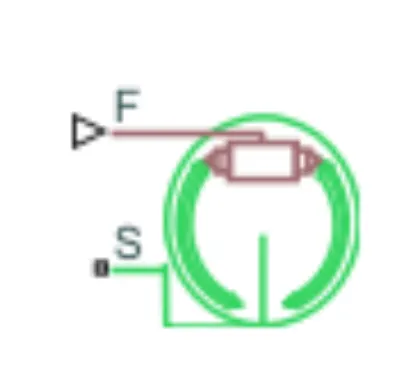
The Double-Shoe Brake block represents a frictional brake with two pivoted rigid shoes that press against a rotating drum to produce a braking action. The rigid shoes sit inside or outside the rotating drum in a diametrically opposed configuration. A positive actuating force causes the rigid shoes to press against the rotating drum. Viscous and contact friction between the drum and the rigid shoe surfaces cause the rotating drum to decelerate.
Double-shoe brakes provide high braking torque with small actuator deflections in applications that include motor vehicles and some heavy machinery. The model employs a simple parameterization with readily accessible brake geometry and friction parameters.
You can also enable faulting. When faulting occurs, the belt will exert a user-specified force. Faults can occur at a specified time or due to an external trigger at port T.
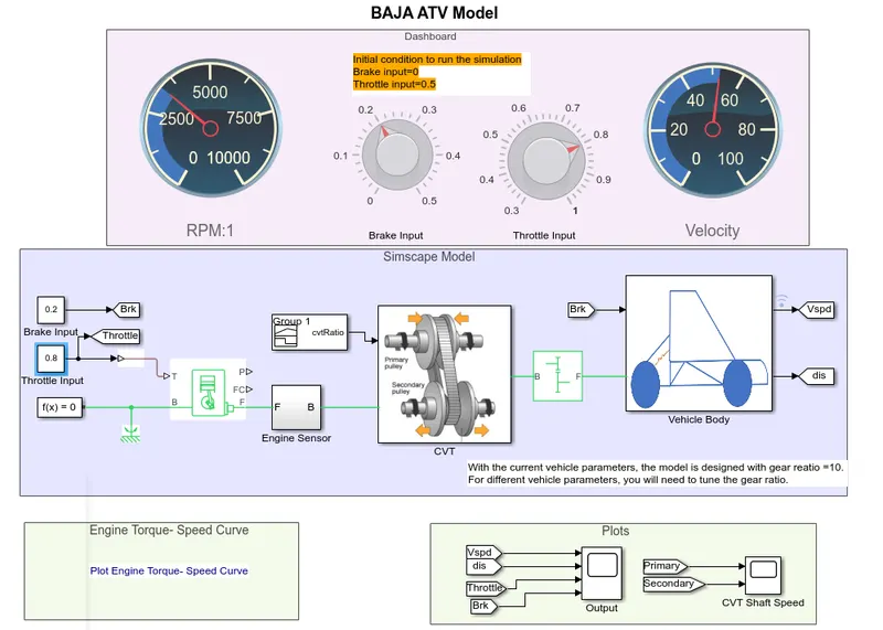
Study the Baja ATV model with a dashboard-
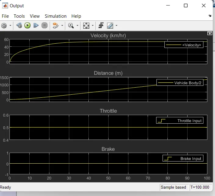
i)case-1: Brake input-0 and Throttle input-0.5
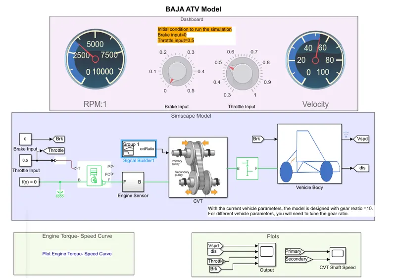
In this model, we have a dashboard that contains knobs to control the Throttle and Brake inputs. In this case, the inputs are not provided using the signal builder. A constat block is provided to control both the parameters in real-time for the user. One can vary it as they want and will get the result according to that.
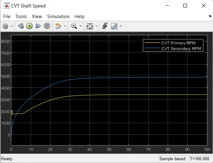
In the Above Simulink Model, RPM(Speed) gauge,Brake Input gauge, Throttle Input gauge and Velocity gauge is Connected in the dash board. Brake input is O and Throttle input is 0.5 for Initial Condition to run the Simulation. Dashboard is connected with BAJA All terrain Vechicle using CVT in Simulink Model.With the help of Dashboard, variation of Speed and Velocity will display in the RPM:1 gauge and Velocity gauge, while running the Simulation. RPM gauge refers the Speed of the Primary & Secondary Pulley and Velocity gauge refers the Speed of the Vehicle.
Output:
i)PLOT ENGINE TORQUE-SPEED CURVE:
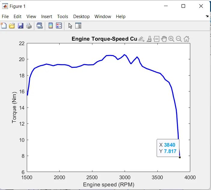
In the above plot Maxximun Velocity teaches at 3840 RPM Vehicle Speed is depends on CVT Ratio.
VEHICLE SPEED PLOT:
in the above Plot,Given input of Brake Input is O and Throttle Input is 0.5 for 100 sec, Velocity will reach 53(km/hr) at 40sec and by keeping the brake input value constant, then velocity value will increase and it reaches the maximum velocity.
CVT SHAFT SPEED PLOT:
In Continously Variable Transmission (CVT) Variator of Primary Pulley goes inward and Secondary Pulley goes Outward it will leads to Overdrive. Primary Pulley radius increases and Secondary Pulley radius decreases So Speed of Primary pulley is greater than Secondary Pulley.
ENGINE SPEED:
In the above Plot, Brake Input is O and Throttle input is 0.5 for 100 sec Engine Speed will decrease at the begining because of increasing gear ratio which increases the torque and by increasing the Throttle input value to 0.5, then Engine Speed value will increase and it reaches the maximum Speed.
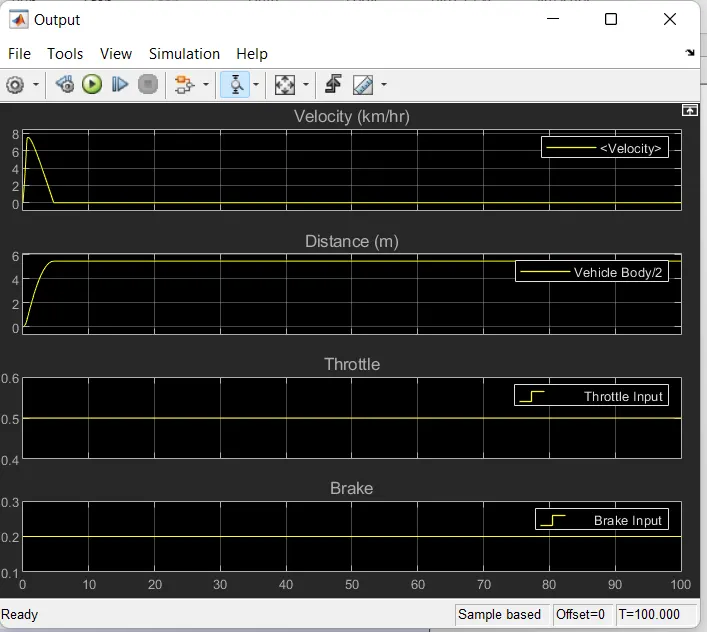
ii)Case-2: Brake input-0.2 and Throttle input-0.5
VEHICLE SPEED PLOT:
in the above Plot,Given input of Brake Input is O.2 and Throttle Input is 0.5 for 100 sec, Velocity will reach 7.56(km/hr) at 0.12sec. By keeping the throttle input value constant and brak input is 0.2 then velocity value will decrease.
CVT SHAFT SPEED PLOT:
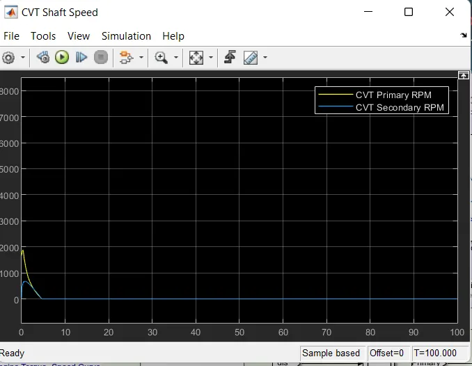
In Continously Variable Transmission (CVT) Variator of Primary Pulley goes outward and Secondary Pulley goes inward it will leads to slowdrive. Primary Pulley radius decreases and Secondary Pulley radius increases So Speed of Primary pulley is lower than Secondary Pulley.
ENGINE SPEED:
In the above Plot, Brake Input is O.2 and Throttle input is 0.5 for 100 sec, Engine Speed will increase at the begining because of decreasing gear ratio which decreases the torque and by kepping Throttle input value to 0.5.
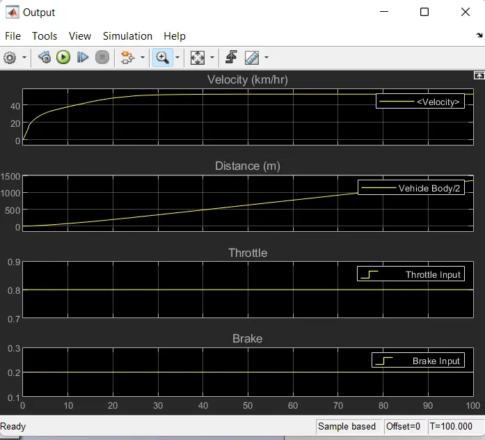
iii)case-1: Brake input-0.2 and Throttle input-0.8
VEHICLE SPEED PLOT:
in the above Plot,Given input of Brake Input is O.2 and Throttle Input is 0.8 for 100 sec, Velocity will reach 7.56(km/hr) at 0.7sec. By keeping the brake input value constant and throttle input is 0.8 then velocity value will decrease.
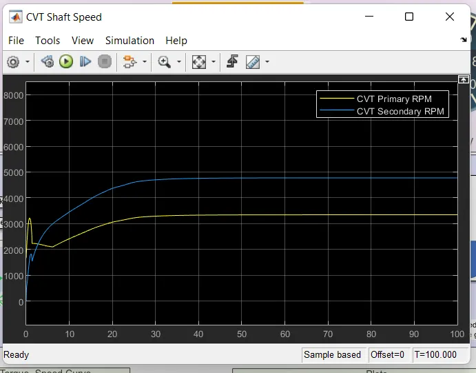
CVT SHAFT SPEED PLOT:
In Continously Variable Transmission (CVT) Variator of Primary Pulley goes inward and Secondary Pulley goes outward it will leads to overdrive. Primary Pulley radius increases and Secondary Pulley radius decreases So Speed of Primary pulley is higher than Secondary Pulley.
ENGINE SPEED:
In the above Plot, Brake Input is O.2 and Throttle input is 0.8 for 100 sec, Engine Speed will increase at the because of decreasing gear ratio which increases the torque and by kepping Throttle input value to 0.8.
CONCLUSION:-
In real-world application is very important to understand the relation between the engine speed (rpm), the gear ratio, and torque. The acceleration and speed requirements can be met by varying the throttle(engine power) and the gear ratio.
For example in case 2 when the vehicle speed was decreased due to the application of brake we applied throttle in order to accelerate but due to the less torque at lower gear ratio the acceleration was not achieved, while in case 3 the gear ratio was increased with the decrease in speed to meet the torque requirement and we saw that the vehicle was able to accelerate.