Project
AIM:- To understand and give a detailed explination of the given ATV simulink model and its working principles.
- there are 5 slx models given in the zip file containing all the data files of the input parameters and operational parameters that are feed to the data file.
Introduction:-
An ATV is abbrivated to an ALL-TERRAIN VEHICLE is a offroading vechicle that is made to takel very harsh terrains. they have very heigh ground clearences and powerful suspension systems. their engines are mainly designed to have a very heigh torque value so that the pulling capicity is very great but in exchange for the overall speed the vehicle can acclerate to. Generally these vehicles can be designed to look like 4 wheel bikes or have a skeleton frame car like structure as seen below.
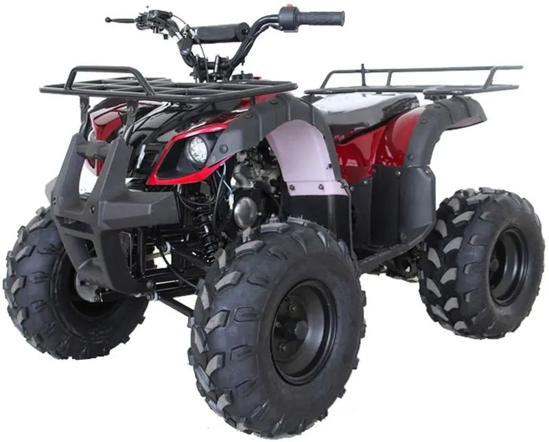
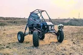
The Baja SAE is a vehicle compitation conducted by the Society of automotive engineers . For this report the model used to control the breaking and throttle response has been given with all required models.
Blocks Used in the model:-
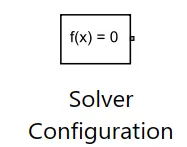
Solver configuration: to specify the solver parameters before starting the simulation
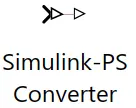
simulink to ps converter and ps to simulink converter: this converts signals to physical inputs and vice versa . so it converts simscape to simulink readable input and vice versa .
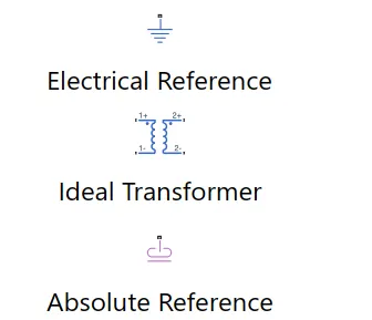
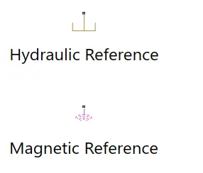
References (all catogery): they based on the models used mostly give a frame of reference to create a constant for reference.
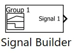
signal builder: using this we can generate a multiple input value that varies with time and there are various pre defined inputs available such as step, noise, ramped etc.
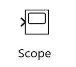
scope: it takes the outputs and graphically displays it.
display: displays a single output value . multiple single outputs can also be connected but only shows the single value.
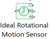
rotational motion sensor: to sense the rotational motion from the given inputs or signals as rpm.
PS constant: a phisical constant value is given to be an input. note that we can use arreys or import the values from our work space .
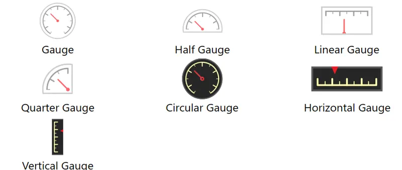
Coustom gauges: it measures the break and throttle input . in this we use it like pedels.
lookup table: the CVT values can be imported or inserted using the workspace.
setup: it increases or decreases at given time intervals.
knob: its used to control the input .
rotational free end: it represents mechanical components. in this case tires.
ps terminator: it terminates the unconnected physical outputs.
inertia: represents the inertial cparameters.
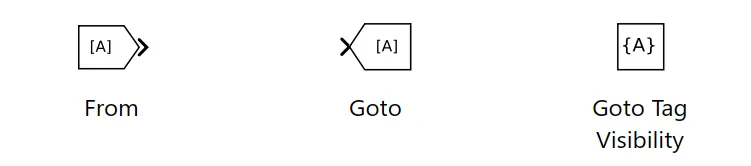
Goto and from:- these blocks accept and send the data across various coustomised blocks.
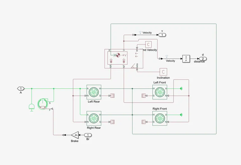
Vehicle Body:- This block contains all the vehicle static and dynamic forces and contain blocks having the magic formulae and tire forces , duuble shoe brake -Represents a brake arranged as two pivoted rigid shoes symmetrically installed inside or outside a drum and operated by one actuator. The actuator force causes the shoes to exert a friction torque on a shaft connected to the drum.
Simple gear :- Represents a fixed-ratio gear or gear box. No inertia or compliance is modeled in this block. You can optionally include gear meshing and viscous bearing losses.
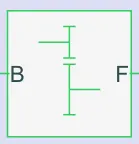
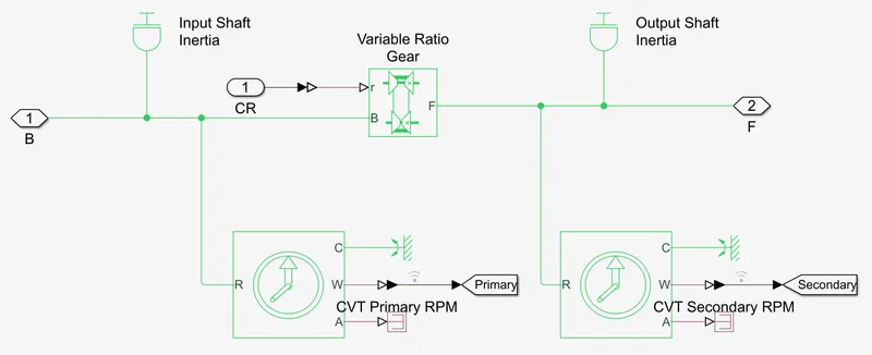
CVT:- continuously variable transmission is an automatic transmission that can change seamlessly through a continuous range of gear ratios. the flexibility of CVT with the control will allow the engine to operate at constant RPM while the vehicle parameters vary. this model is made using ideal rotational motion sensor - This block measures angular velocity or angle in a mechanical rotational network. The sensor is ideal since it does not account for inertia, friction, delays, energy consumption, and so on. and Varied gear ratio block - Represents a variable ratio gearbox such as implemented by mechanical belt CVT, electric, or hydraulic transmissions. The physical signal input r defines the ratio of input to output angular shaft velocities
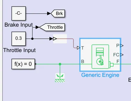
Generic engine block: as the engine is the main part that outputs we feed all the values that we draw from the look up tables and the varying parametes which calculates the engine respones. Represents a system-level model of spark-ignition and diesel engines suitable for use at initial stages of modeling when only the basic parameters are available. Optional idle speed and red line controllers are included.
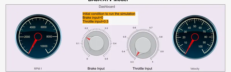
Dashboard:- the dashboard displays and takes the imput values dynamically . it contans the knobs and dials that indicatethe outputs.
OBSERVATIONS:
The engine torque and speed curves are the limits set by the engines indicating its curve for performance. thus the table is used to set the operational limits.
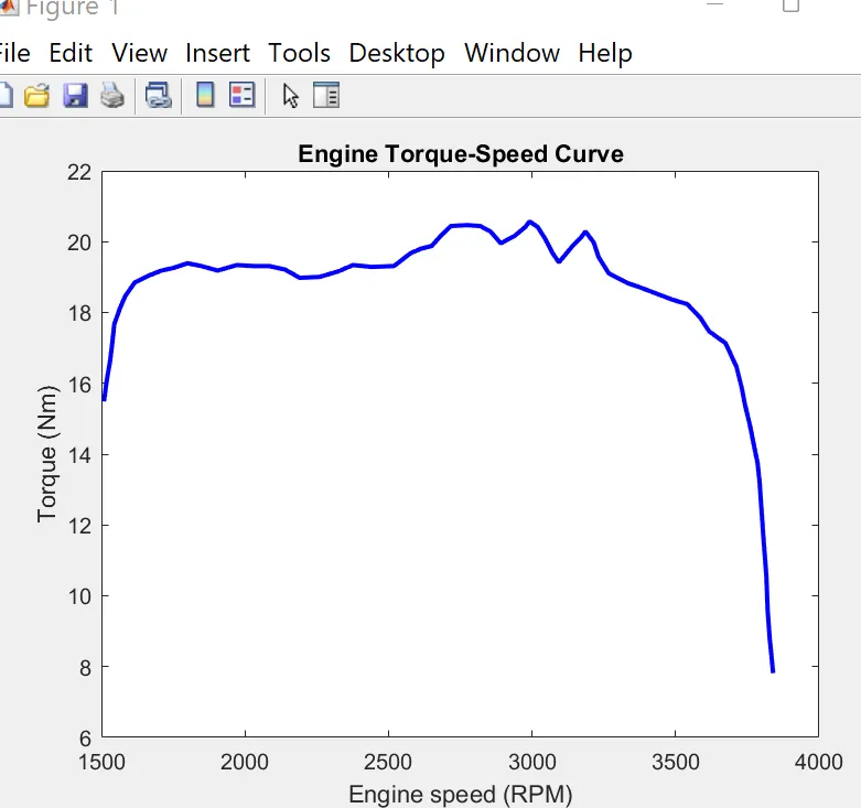
Plots: the plots takes in all the values using goto options and then its displayed in the scope:

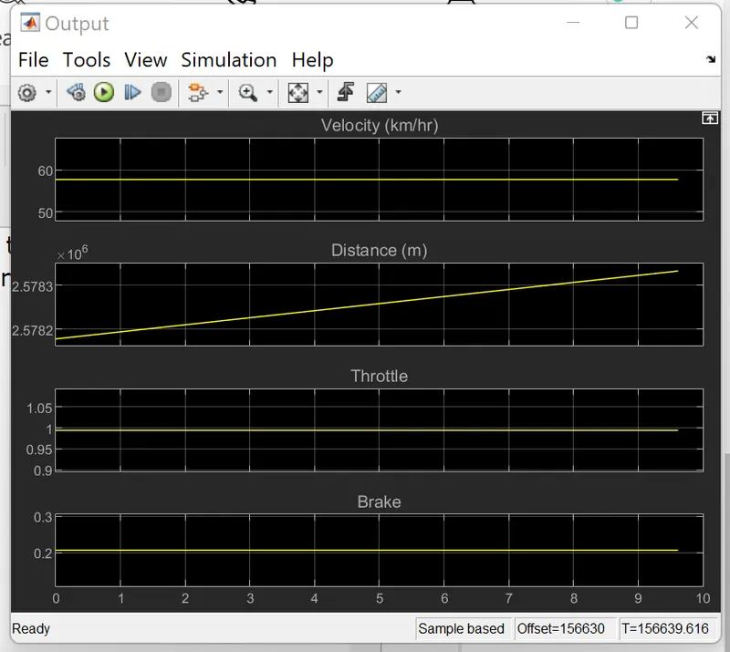
The below graph represents the output that are being used as inputs by the engine and CVT . as the program runs in real time we can see how the respones for the throttle and breaks keeps changing. we can also see that the velocity is maintained without very harsh changes.
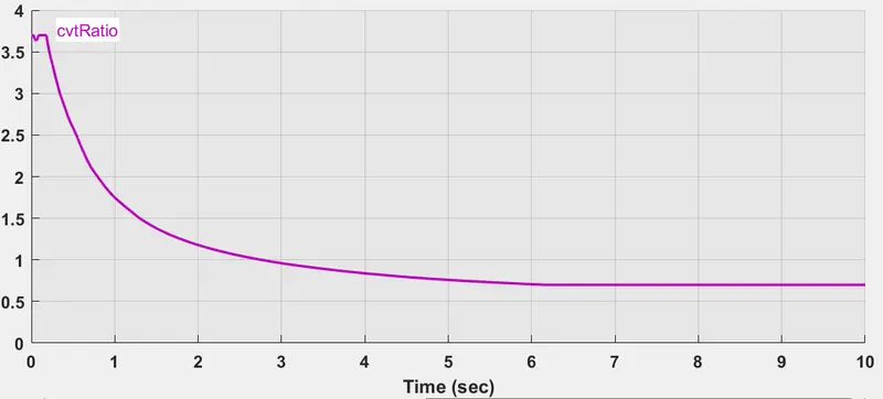
We can also see from the below outputs the the primary RPM is the one actually outputted by the engine while the secondary RMP is the one that is expected by the mathematical calculations which is a lot heigher. Due to losses and the controller to maintain the best possible conditions
The CV ratio is set to be maintained at a max value of 10 .
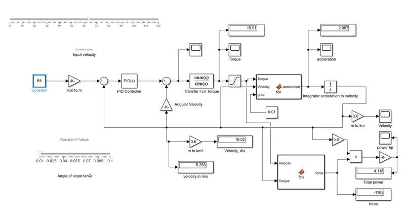
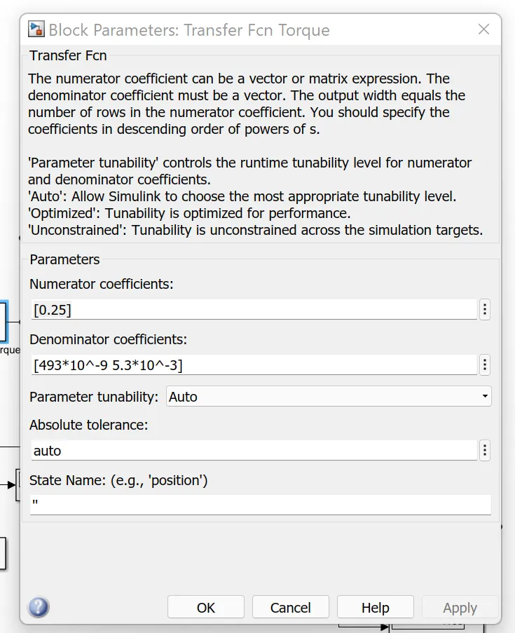
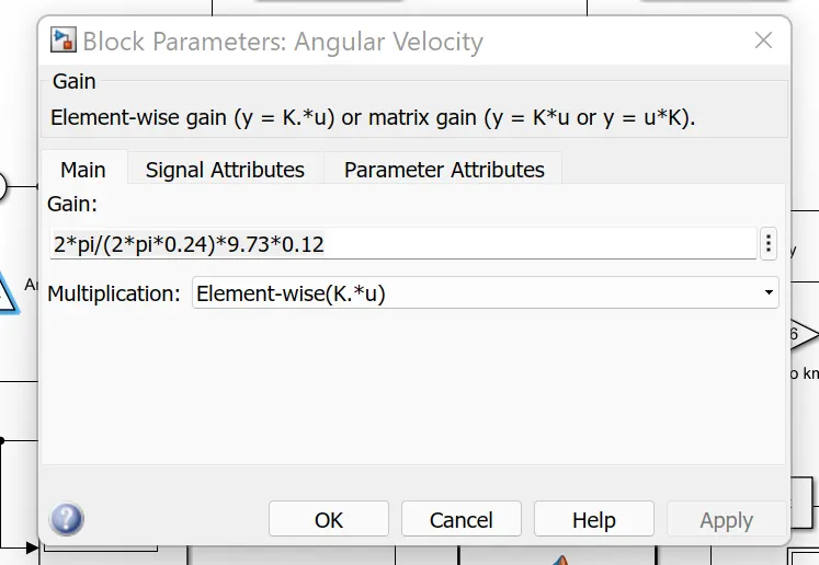
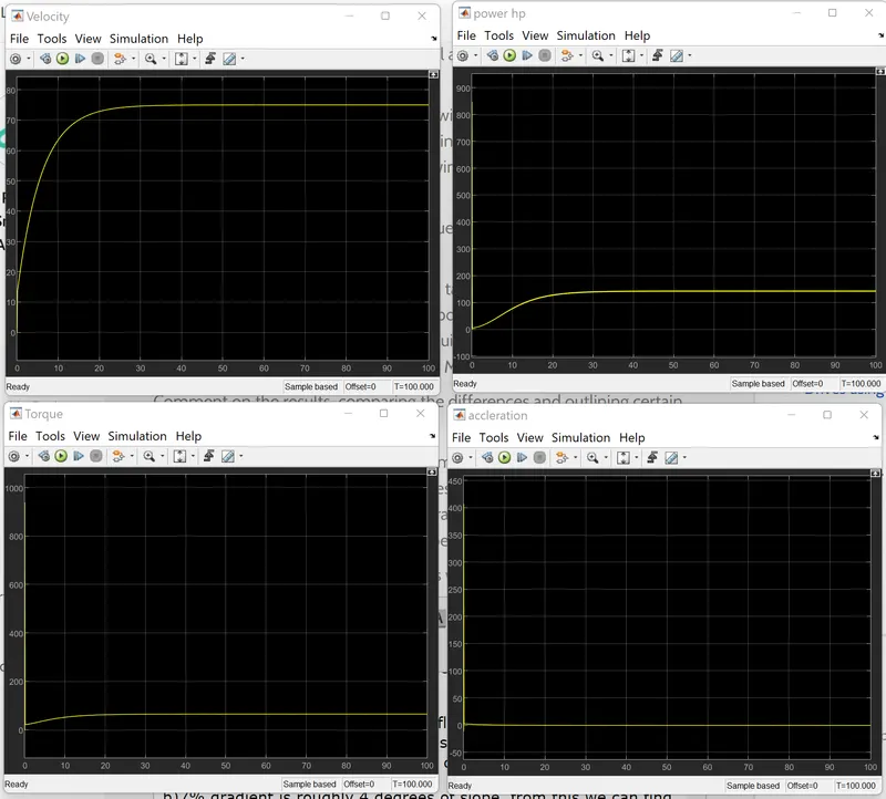
In addation to understanding the above problem, based on the same methods a very simple model is made to control and maintain the speed of an electric car motor. giving the outputs of accleration, torque, velocity and power.
References:-
https://www.youtube.com/watch?v=gOFweQcz0XI&t=1s
https://in.mathworks.com/products/new_products/latest_features.html?s_eid=PSM_15028