Project 3
- Aim : Modelling and simulating a buck converter for auxiliary load in EV.
- Workflow and Equations : The workflow for the model and the equations are as follows :
- We have the input voltage as 48 V and the load current as 10 A and will be using resistor as load for taking the output of 12 V. We use a DC voltage source to provide the input of 48 V and we will be using the MOSFET as the switching device with a diode as the freewheeling diode.
- The inductor and capacitor are used accordingly in the circuit and we use the current and voltage sensor to measure each of them. The pulse generator will give the switching frequency with a specific duty cycle.
- The MOSFET works as a switch in the circuit and charge the inductor as the DC current will rise the inductor will oppose it by creating a potential against the DC source and when the switch is off, the inductor still don't like the degrading current so it creates a potential to sustain that current and the freewheeling diode will complete the circuit.
- The governing equations are for getting the values for the inductor, capacitor values.
- We are assuming that the inductor ripple current will be around 0.3 by the general thumb rule so `triangleI_l = 0.3*I_(max)` . Now we can calculate the inductor and capacitor value.
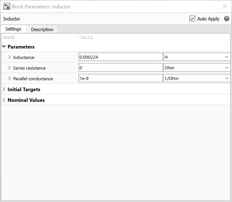
- The inductor will be `L= (V_i*(1-D))/(triangleI_l*f_s` where
- L is the inductor value
- `V_i` is the input voltage
- D is the duty cycle
- `triangleI_l` is the inductor ripple current
- `f_s` is the switching frequency
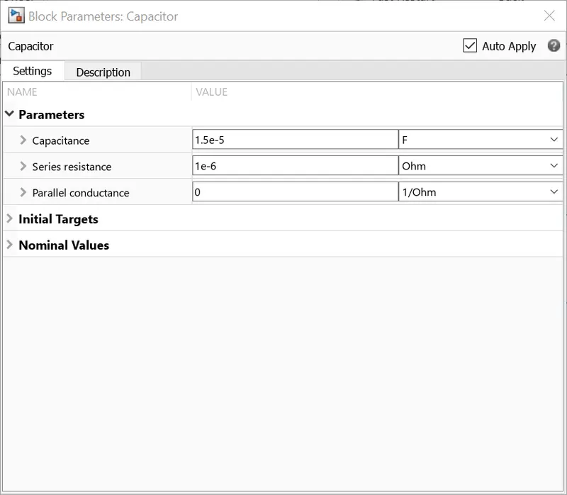
- The capacitor will be `C = (triangleI_l)/(8*f_s*triangleV_o` where
- C is the capacitor value
- `triangleV_o` is the output ripple voltage
- The duty cycle will be output voltage / input voltage, considering this we will be having the duty cycle of 25% but we will be taking the duty cycle as 30% because there will be some voltage drop in the output due to the resistance of the MOSFET and the diode in the circuit.
- Model and Explanation :
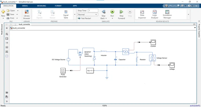
- So now we know the inductor, capacitor and resistor values, we make the required connections as shown in the model. The DC supply is directly given to the switch and the inductor is in series and the capacitor is in parallel to the load.
- As the switch is closed due to reverse biasing the diode will be blocking the current and the inductor will get charged. The capacitor is in parallel so that charge will be accumulated at its plates and also not block the current as it is in parallel. The charge which get accumulated at its plates will move out through the resistor when switch is in off position.
- As the switch is open the inductor will change its polarity, gets discharged and provide current to the resistor and diode will complete the circuit.
- This is the reason the output voltage is duty cycle times the input voltage, the more time the signal is ON the more inductor current and hence we have more voltage at the output.
- The switching for the MOSFET is taken 50 kHz and the duty cycle is set to 30% using the pulse generator block.
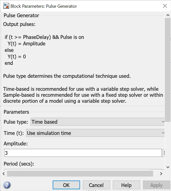
- The MOSFET and diode parameters are kept unchanged while the inductor and capacitor values are set according to the equations.
- We take the output ripple voltage as 0.5 while picking up the capacitor. The output ripple voltage about the output voltage can be up or down then the desired value.
- The voltage and current sensors are placed accordingly to measure the output voltage and current.
- Results :
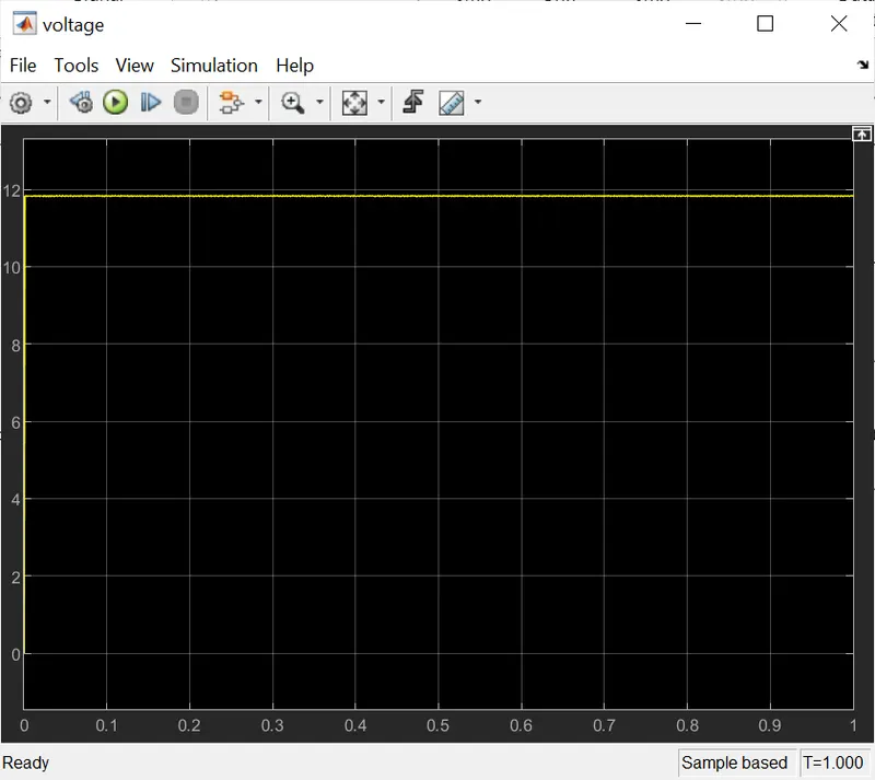
- The voltage is around the desired voltage, the ripples are also quite low.
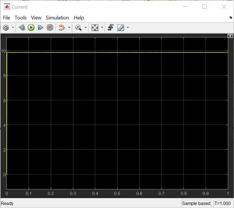
- The current flowing through the resistor is around 10 A. In the buck converter the voltage drops down but the current increases as the input power must be equal to the output power in addition with losses.