Project 3
Aim :Design and simulation of Buck converter for Auxiliary load in EV
Given
- Input voltage is 48V, Output voltage is 12 V
- Load current is 10A
The calculations are done on the to find the values of L C and R
Vin=D*Vout
where Vin- input voltage
Vout- output voltage
D= duty ratio
D= Vin/Vout
=12/48=0.25
Finding inductance value
L=Vout(Vin-Vout)/ΔIl*fs*Vin
Ripple current ΔIl=0.2 to 0.4% of load current=0.4*10=4A
Then L= 12(48-12)/4*1000*48=2.25*10^-3
Finding capacitance
C=ΔIl/8*fs*Vout
=4/8*1000*12=4.16*10-5
Finding value of resistor
R=Vout/Il
=12/10=1.2ohms
The blocks used are
PWM generator
Used to provide pulses to the MOSFET
MOSFET
It is used to control the voltage in the circuit
Diode
Used as free wheeling diode in the circuit
Resistor
The load used is resistor load.
Value of R=1.2ohms
Capacitor
Used to give capacitance in the circuit
C=4.16*10-5
Inductor
Used to provide the purpose of inductor in the circuit.
L=2.25*10^-3
Switching frequency is given as 50kHz
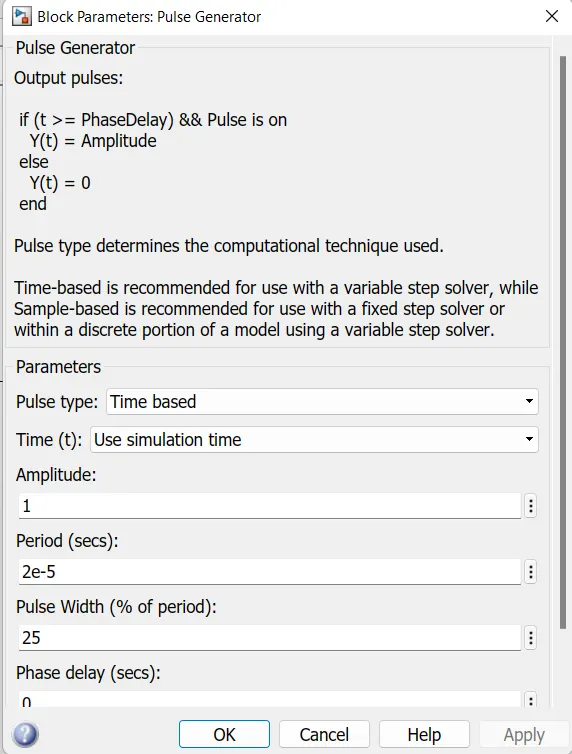
Circuit
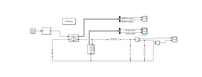
Buck converter:
It is used to step down voltage from higher to lower value.
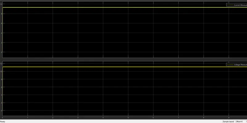
From the output it is observed the aim has been accomplished by converting Input voltage of 48V to 12V