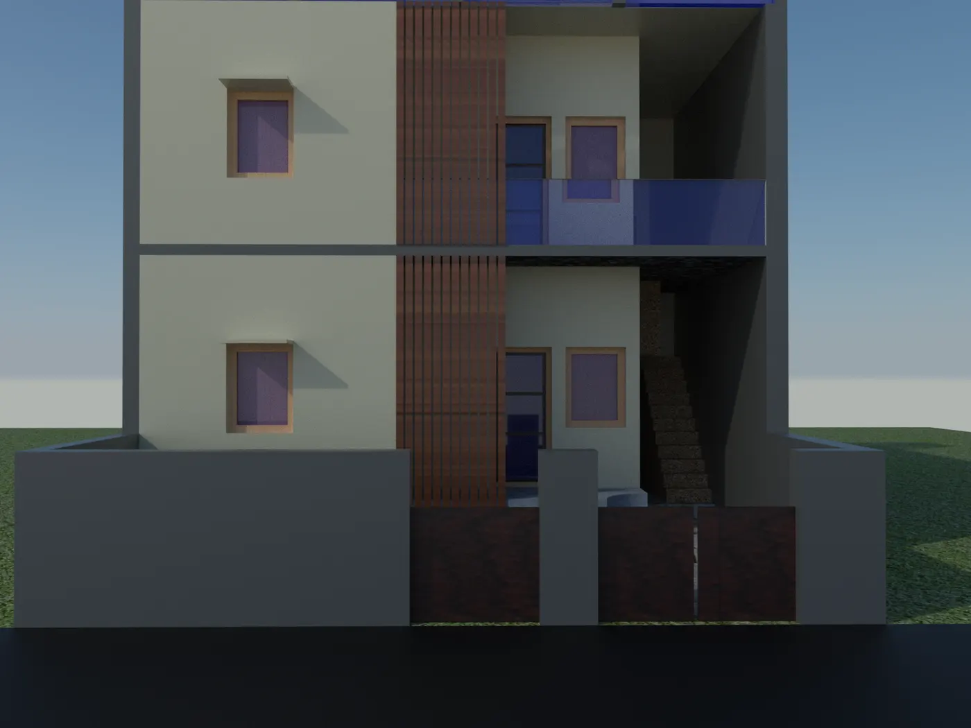
Project 2_Creating a 3D rendered model for a Residential Building in AutoCad
OBJECTIVE:
to construct a three-dimensional rendered view model of the residential structure.
OVERVIEW
- Users that employ 3D models may see virtual pictures of their work and receive a more vivid design.
- A 3D representation of an architecture is far more engaging and accurate than a 2D one.
- When a person views a 3D model instead of a 2D sketch, they get a far more engaging and fulfilling experience. A 3D model allows the user to observe the effects of any changes, whether little and large. Additionally, it helps to finish the designs more beautifully while saving money and time.
- Interior designers are able to create and alter 3D interior and exterior spaces according to their preferences and needs, which is an incredible benefit of using 3D models.
- The user may see an object's actual size and distance from other elements in the layout as a whole while viewing a 3D design. This function is quite helpful in seeing and adjusting object arrangements according to their sizes.
PROCEDURE:
- To begin with, launch AutoCad by selecting the AutoCad application icon with the Windows key.
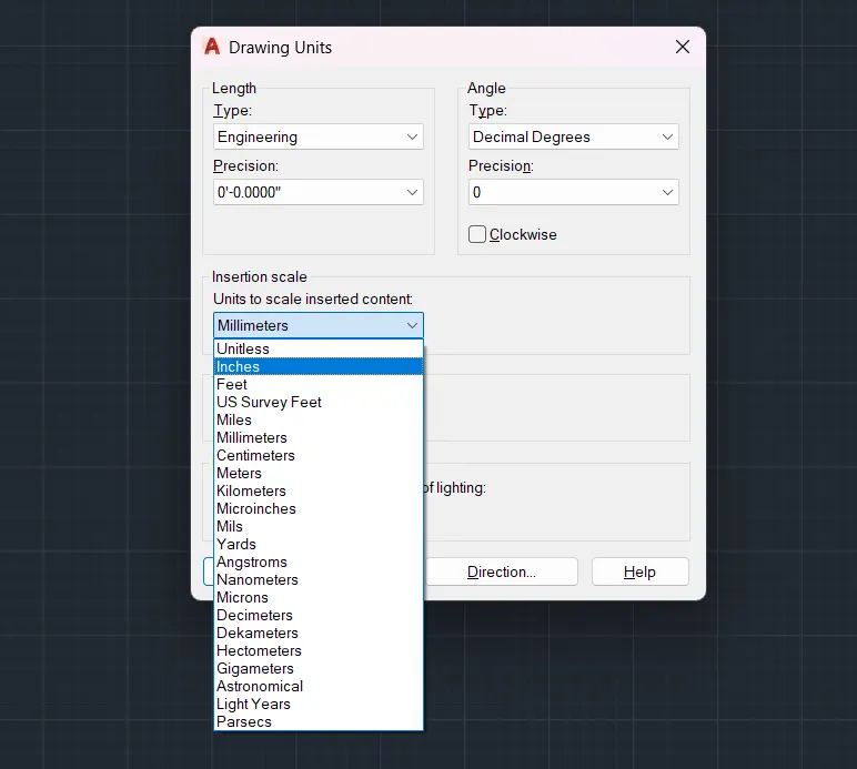
- Next, start a fresh sketch using imperial units.
- Next, use the UN shortcut in the command box to fix the UNITS.
- Fix the Select to Engineering and the insertion scale to Inches in units.
- Next, use the Limits command to fix the LIMITS.
- The workspace is then zoomed in by using Z-Enter and A-Enter.
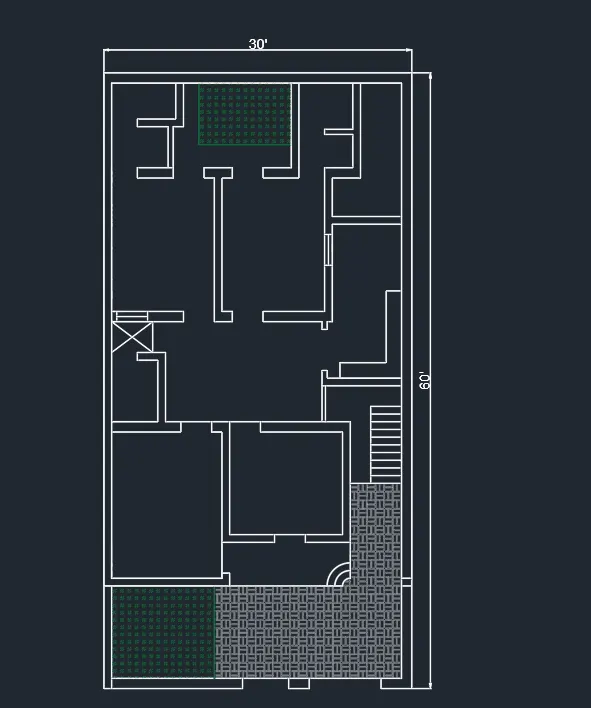
- Next, create the residential building's 2D plan.
- Use the BOUNDARY command to pick the wall areas after the plan has been produced, then fix the selection as a REGION.
- Next, choose the regions that comprise the wall by clicking on Pick Points.
- When using AutoCad, creating levels for various components is also crucial.
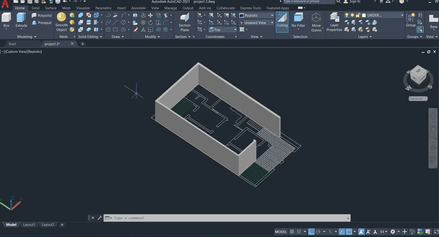
- After that, go to the 3D MODELLING workspace.
- Next, choose the extruded wall sections with the EXTRUDE command, and then extrude it.
- Next, make the 3D model's DOORS & WINDOWS.
- Draw the height and width of the window. by drawing using the LINE or Rectangle commands.
- Next, offset the frame border inside to 3" after offsetting the frame inside to 2". Finally, create the centre line for the frame border line in the z direction.
- Next To build a region for a frame, use the BOUNDARY or REGION commands.
- Use the SUBSTRACT command to eliminate the region from the panel and multiples to fix it only for one frame.
- Once the substract command has been used, choose the desired region or large region, pick the undesirable area, and then input the relocated region.
- You may use this step for doors as well as windows.
- Apply the material for the designated area or part after it has been created.
- Use the MATERIAL BROWSER for that, then choose the desired material from the browser and apply it to that specific area.
- After making windows and doors, precisely place them.
- Next, sketch the area of the roof slab using the PLINE OR RECTANGLE command.
- Next, turn that into a region by creating a polyline or rectangle inside the region using the BOUNDARY or REGION commands.
- After that, extrude it using a 6-inch-thick slab.
- After that, the first floor plan is drawn using the same procedures.
- Draw the staircase's face in the XZ plane, create an area, and then extrude it to a width of 4'.
- Once it is created, place it in the designated spot.
- Apply the substance to each component after completing the previously mentioned stages.
- To do that, apply materials to the wall, such as paint, tiles for flooring, etc., using the MATERIAL BROWSER.
- Next, use the LIGHTS command or the VISUALISE tab to choose the LIGHTS from the panel in each room you wish to set the lights in.
- Next, decide what kind of lighting you want. If I want POINT LIGHT, I should pick it, then move the light area, give it a name, then click OK.
- Once it is created, choose the light point and modify its parameters.
- Then, click on sunlight enable after turning the lights to off if you desire daylight.
- after completing all of this. Proceed to render our model building's outcome.
- Next, select VIEW MANAGER to construct the various building views.
- Next, choose the desired view and make it the active one.
- If you want to view your building in the daylight, switch off the lights and let the sunshine in.
- Next, the renderer's RESOLUTION to obtain a distinct rendering perspective and picture.
- Next, render the building by using the RR command or by clicking the RENDERING button.
- Save it in your file manager when it has been rendered.
SCREENSHOTS
UNIT SETUP AND DIMENTION SETTINGS
2D PLAN
We have created the floor plan for the home 3D model using commands like line, dtext, adc, dimlin, trim, copy, polyline, block, block edit, mirror, offset, layers, and hatch.
CONVERTING TO 3D
CREATING BOUNDARY WALLS AND FLOORING
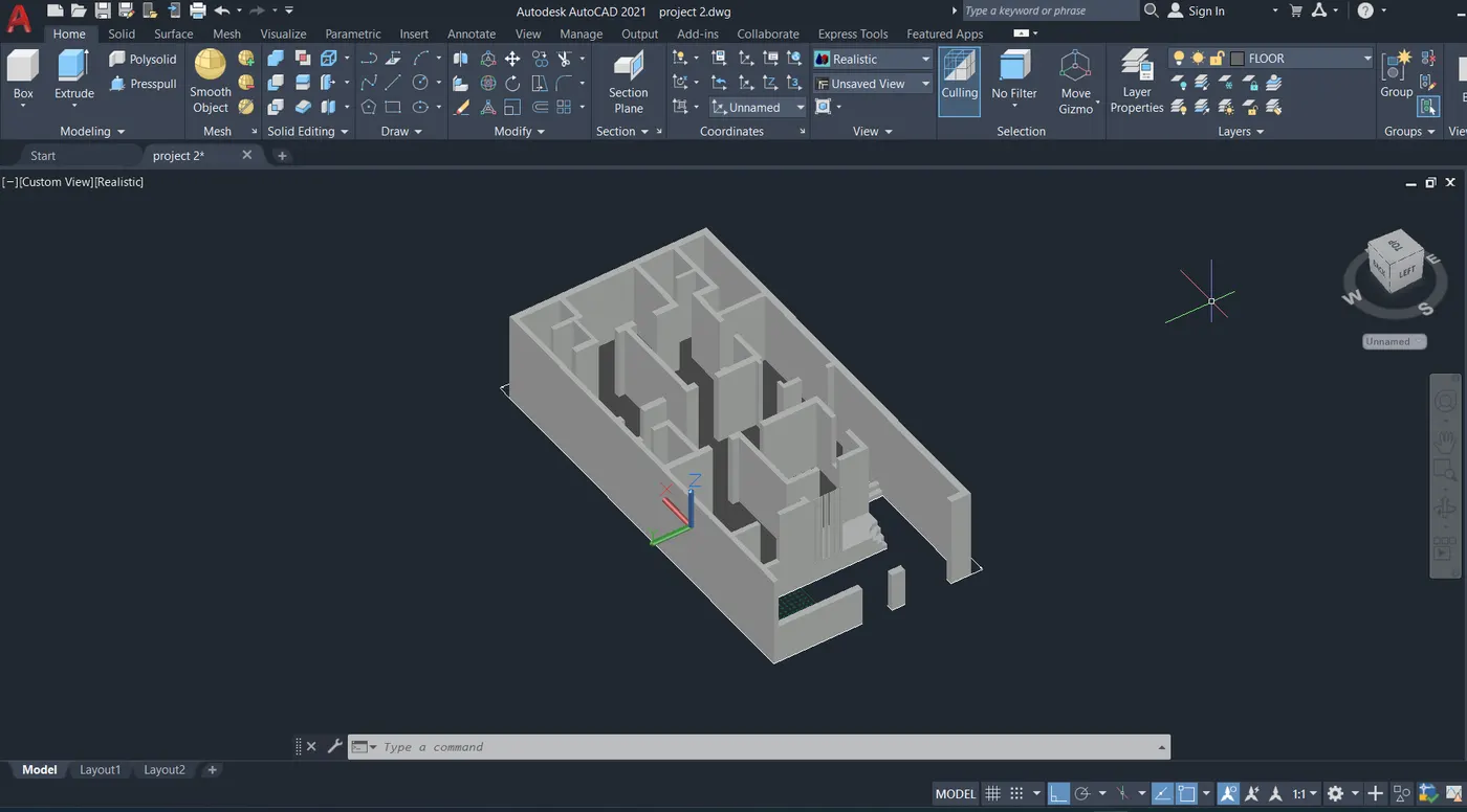
ADDING GRASS AND MAKING DOORS
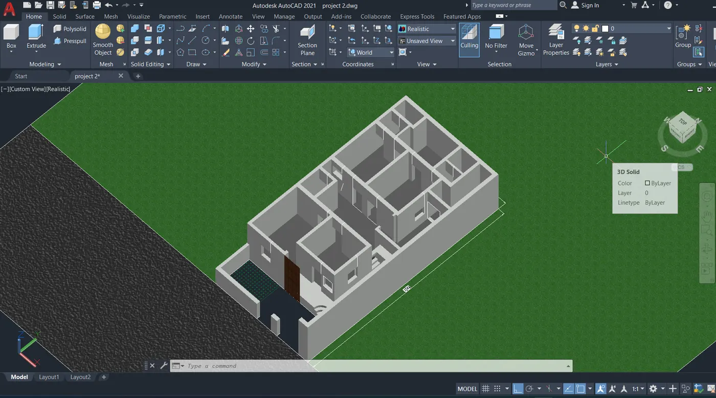
ADDED THE FIRST FLOOR
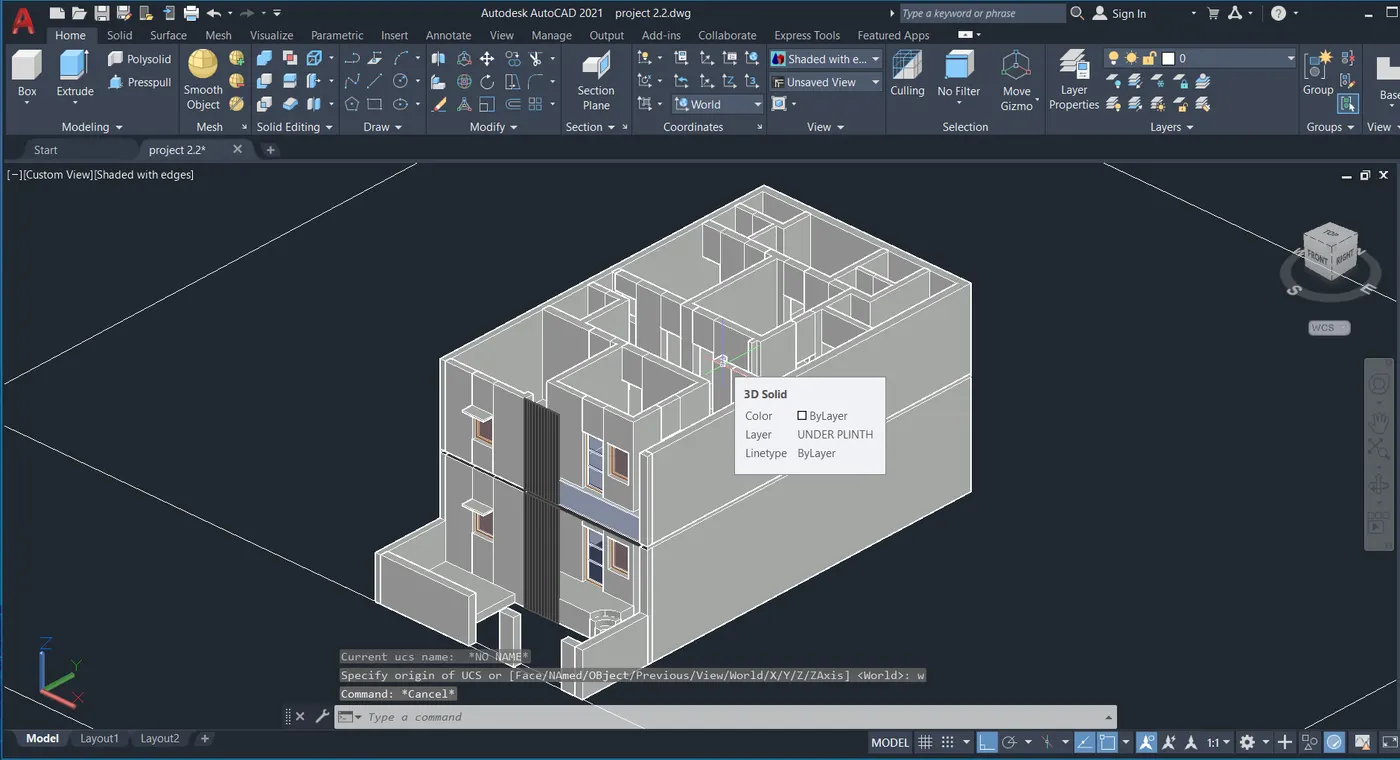
FINAL MATERIAL SELECTION
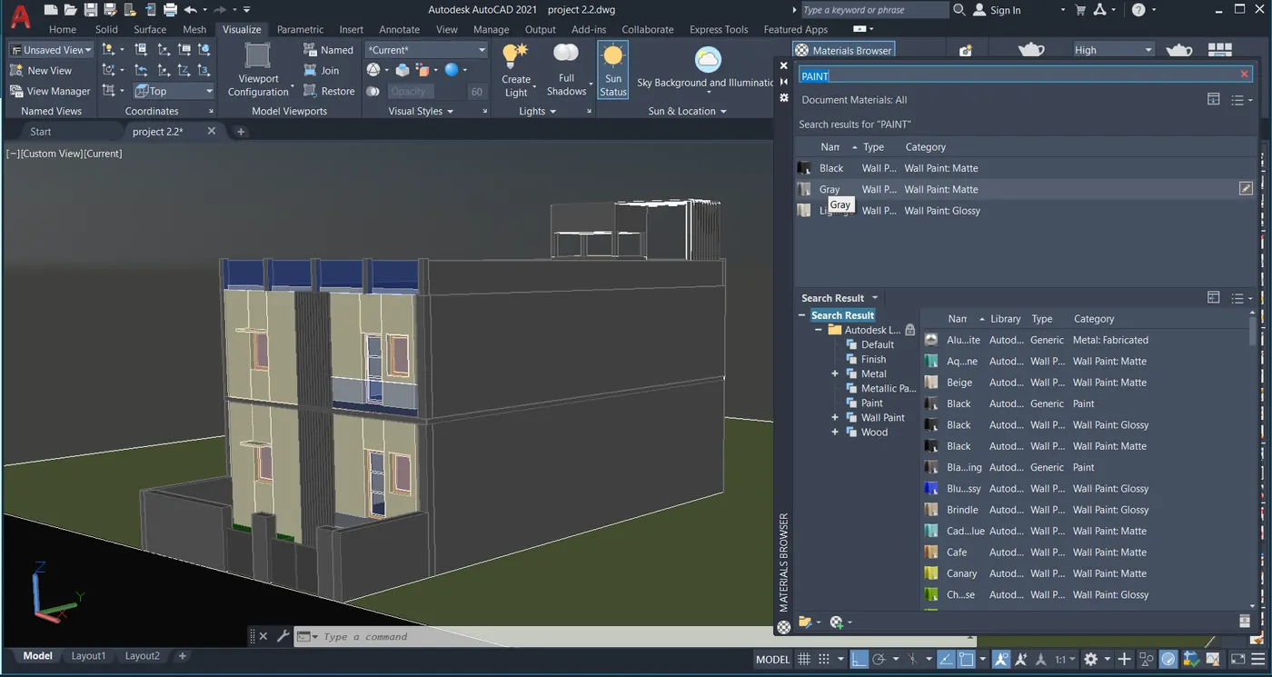
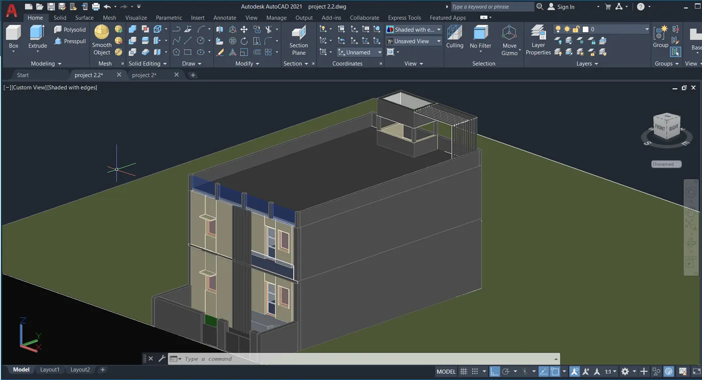
ADDING THE LIGHT AND THE CAMERA
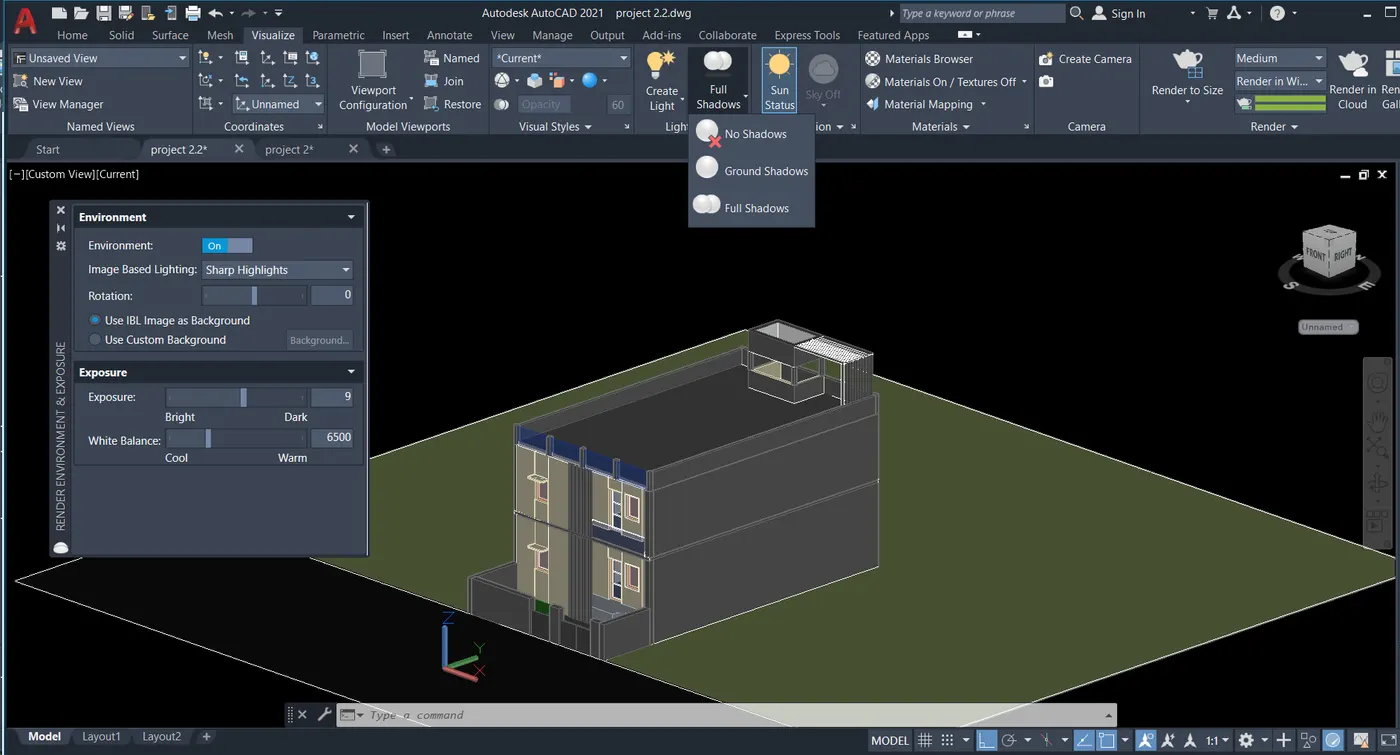
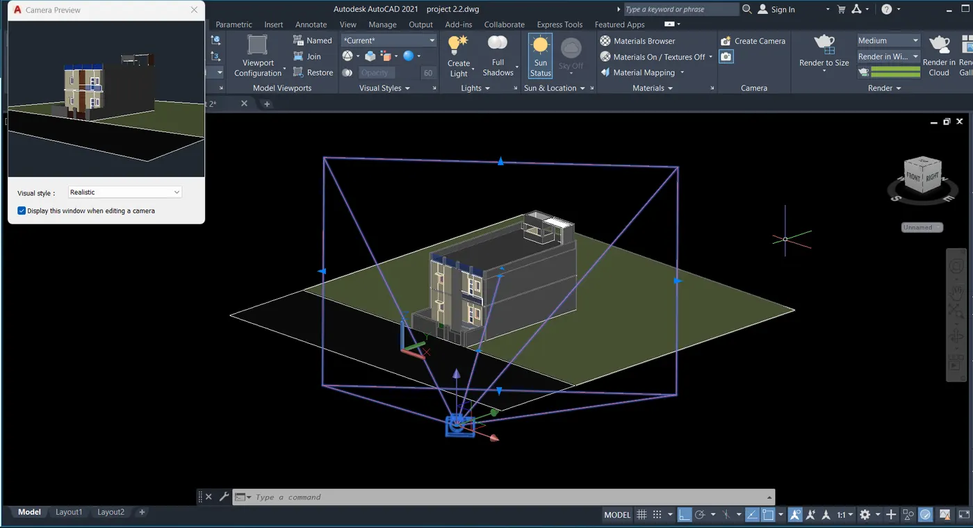
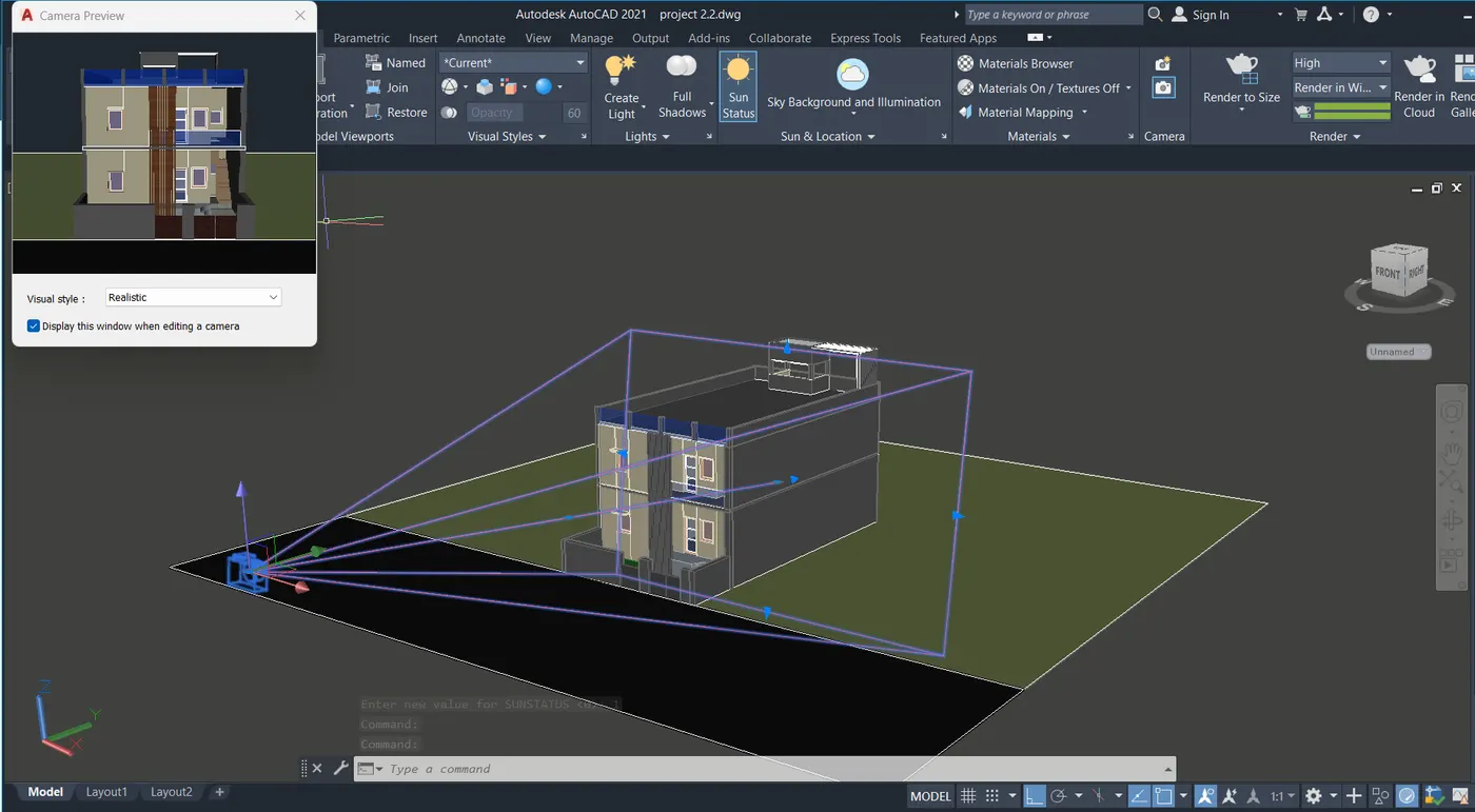
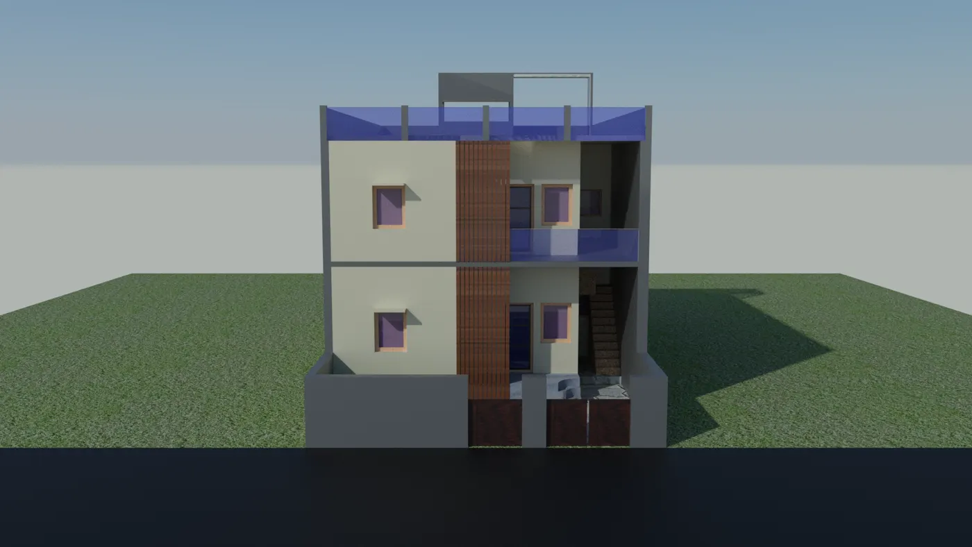
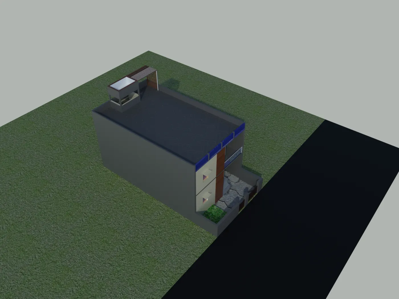
RENDERING THE FINAL PRODUCT WITH THE CAMERA VIEWS
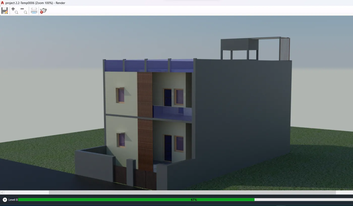
FINAL 3D RENDERED OUTPUTS
FRONT VIEW/ ELEVATION
ISOMETRIC VIEWS
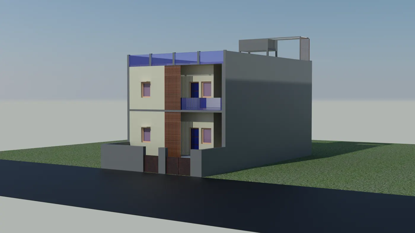
CLOSEUP