Project 2 Thermal modeling of battery pack
AIM: Thermal Modeling of Battery Pack.
Objective:
- For a 10 cell series lithium ion battery model, simulate the thermal effects and compare life cycle performance at various temperatures, charge & discharge rates using MATLAB.
Introduction:
The performance and life-cycle costs of electric vehicles (EV) and hybrid electric vehicles (HEV) depend inherently on energy storage systems such as batteries. Battery pack performance directly affects the all electric range, power for acceleration, fuel economy, and charge acceptance during energy recovery from regenerative braking. Because the battery pack cost, durability, and life also affect the cost and reliability of the vehicle, any parameter that affects the battery pack must be optimized.
Temperature and temperature uniformity have a strong influence on battery pack performance and consequently, that of HEVs and EVs. All the modules in the pack should be operated within the optimum temperature range suitable for the particular electrochemical couple used. In addition, uneven temperature distribution in a pack leads to different charge/discharge behaviour that results in unbalanced modules and reduced pack performance . Because HEV batteries have high specific power and undergo aggressive HEV charging/discharging profiles, thermal issues in an HEV pack are of more concern than in EV packs.
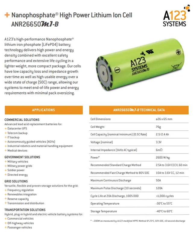
In this project will simulate the thermal effect of a 10S1P lithium-ion battery pack,which consist of 10 ANR26650m1-B high-performance Nanophosphate lithium iron phosphate (LiFePO4) battery technology delivers high power and energy density combined with excellent safety performance and extensive life cycling in a lighter weight, more compact package. to make its interesting,a fault has been introduced in one of the cell to demonstate the effect of the faulty cell on the entire pack.
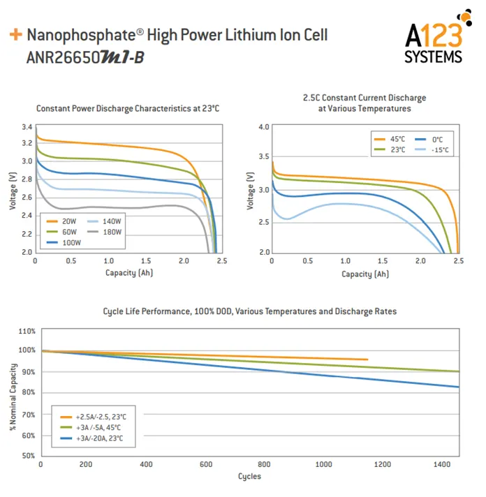
ANR26650m1-B Nanophosphate lithium iron phosphate (LiFePO4) datasheet used for this project:
What is Fauly Cell ?
A faulty cell demonstates performance that is different than the other cell usually most cell will be displaying the same SOC ,temperature voltage level etc.but a faulty cell will show sign of overheating,faster discharge(due to reduced capacity or reduced OCV) oe will be unbalanced cell.this will be impact the performace of the entire pack as the faulty cell will limit the pack from utilizing its maximum potential.

in this project the faulty cell is repesenting by adding an extra external resistor.this will make the cell react diffirently then the other cells.
Simulink Model:
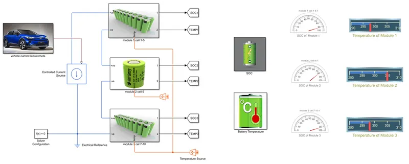
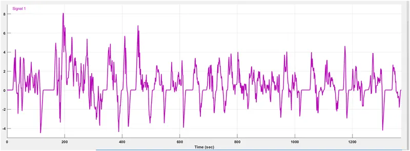
- in this model 1st we give UDDS current profile to battery pack with help of signal builder block.
- UDDS cycle (current vs time) has been used to charge discharge the batteries for given periode og time 1370 sec.
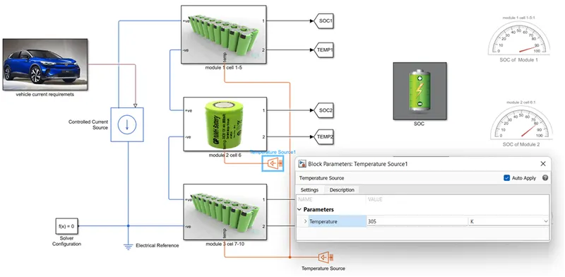
- there is three module hav been connected together in series to make a 10 cell battery pack model.
- in cell no.6 a resister can be added to vary the rate of discharge.
- all cell are configure same as ANR26650m1-B cell .it means put same value which in datasheet.
- all cell are iniially at 25 degree c.a temp.source is used to test the cell performance at 3 different atm.temperature,like At 25oC,At 45oC,At -10oC .
- convective and conductive block hae been added for heat transfer between blocks.
vehicle Current Model:
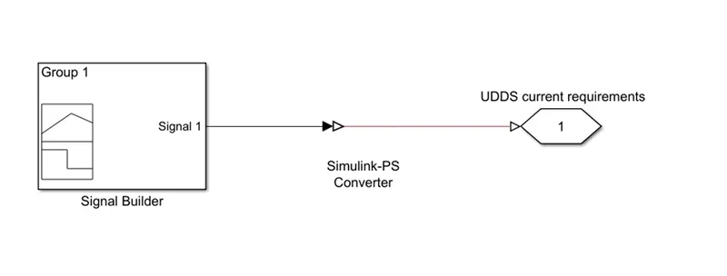
- In vehicle current requirement subsystem block,the signal builder block used to apply UDDS current profile and simulink-ps converter block used to convert the simulink signal to physical signal.connectin port block used to output the signal.
Thermal modelling of battery pack:
A 10-cell series Lithium-Ion model images is shown below. It showcases a battery pack. Here in this model, we will simulate the thermal effects and compare State of Charge (SOC) and Temperature using charge and Discharge cycle at various temperature conditions.
Thermal modelling of battery pack is very important as it gives a clear idea about thermal behaviour of a battery pack which hold a very high value because it helps make a battery pack more reliable and safer specially in case of Lithium-Ion battery which can go thermal run away if not properly managed. A thermal run away will lead to fire which will destroy the Electric vehicle completely and a customer will lose a value money invested which will drive the masses away from using EVs.
EFFECT OF TEMPERATURE ON LITHIUM ION BATTERY:
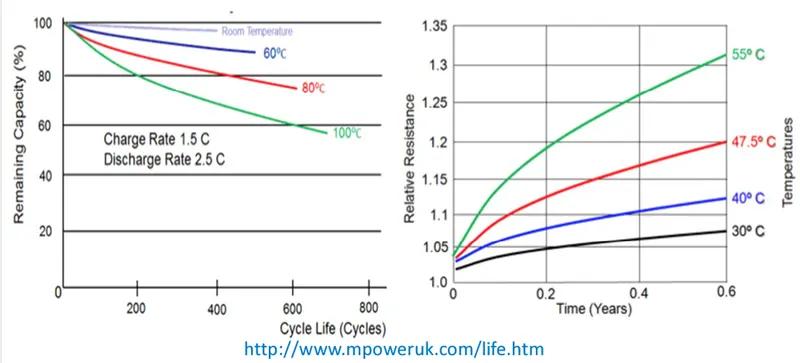
- High temperature reduces the life cycle of the battery.
- High temperature reduces the capacity of battery over time.
- The resistance of the battery increases over time with increase in temperature.
- Due to high temperature the cost to drive EVs over time increases.
The below image will summarise the above points.
TEPERATURE IMPACT ON EVs:
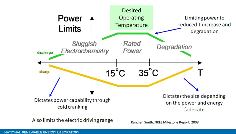
- High temperature degrades the life of lithium-ion battery more quickly.
- Lower temperature ranges reduce the capacity and power of the lithium-ion battery.
- Proper temperature range between 15 °C to 35 °C gives the rated power and capacity.
The below image will give a clear idea about the above points.
For normal operation of an Electric Vehicles a Battery Management System and a Thermal Management system is needed.
Battery Management system is the main brain of the battery pack and Thermal Management system is a subsystem of Battery Management system (BMS) which reports temperature of each cell, module and pack to BMS then BMS takes all the necessary action to bring the temperature of battery pack at optimal temperature range by performing several operations like checking for voltage, current and temperature of each cell and selecting right action for Battery Cooling System. BMS also serves as data centre for reporting and calculating.
BATTERY THERMAL MANAGEMENT SYSTEM
- The high battery temperature leads to poor performance, short lifetime, and risk of blasting. Therefore, a BTMS is essential for all battery modules.
- The main purpose of a BTMS is to maintain the battery system in the optimum temperature range and keep uniform temperature variation in the battery modules.
- Prevent the cells from going above or below acceptable limits.
- It should help to maximize the useful energy contribution from each cell.
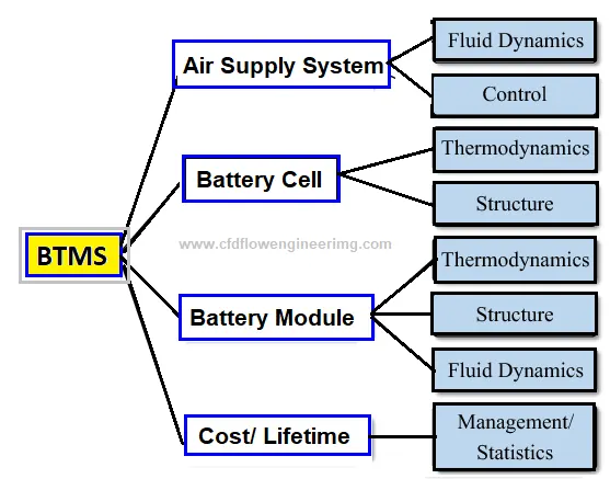
The following figure shows the most used thermal management techniques for battery module.
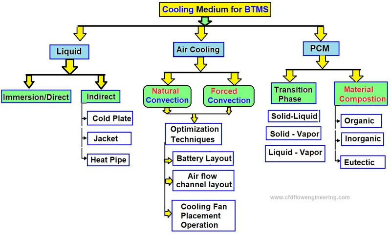
For better adaption to EVs, BTMS must ensure features such as high performance, simplicity, low weight, reduced cost, fast packaging and easy maintenance. Two types of battery cooling systems (BCS) are common which are external or internal. External Battery cooling systems (EBCS) are classified into several different ways
Battery cooling can be categorized based on the method or technique.
THE MODEL OF 10 CELL IN SERIES FOR THERMAL OBSERVATION:
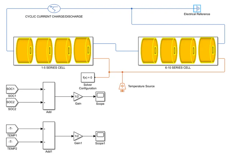
In the above model an AC Current source block is used for giving cyclic input of current for charging and discharging the battery in series. Two Subsystem Block is used where 10 cells are arrange in series along with thermal network. An Electrical Reference Block it represents the Electrical ground for all the electrical elements, Electrical conserving ports of all the blocks that are directly connected to ground must be connected to an Electrical Reference block. A model with electrical elements must contain at least one Electrical Reference block. Solver Configuration Block it specifies the solver parameters that the model need before the simulation begins. Temperature Source Block is use to give a temperature to 2 subsystem blocks where the battery is connected in series. Gain Block is used to get the average from the input signal along with these blocks Goto and from block are used to get the signals from Subsystem Blocks.
The two subsystem blocks are connected in series and signal is given using AC Current source.
MATLAB Code:
clear all
close all
clc
f1 = xlsread('UDDS current profile (2).xlsx');
time = f1(:,1);
current= f1(:,2);
UDDS Current Profile in Signal Builder:
Module 1 [Cell 1-5]:
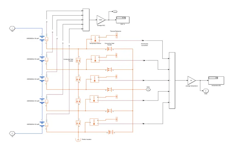
- In this module we used the 5 table based battery block in which we put the datasheet value on it.here i put the battery specification like, 2.5Ah capacity,initial temp.value is 298K etc.and this 5 cell are connected in series.
- also here we use the conductive heat transfer block in which we put the thermal conductivity is 401 W/(K*m),area is 10 m^2,and thickness is 0.1m.
- here we use the convective heat transfer block in which we put the heat transfer co-efficients is 20 W/(K*m^2),area is 10 m^2.and one end of this block is connected to thermal source and other is connected to perticular cell.
- here we use perfect insulator also.
- here we use temperature sensor to sense the temperature of cell and display the value in scope and dashboard.also it one end connected to thermal referance.
- and SOC of every cell is also calculate by using add and gain block,and display the soc value in % in display block.
Module 2 [Cell 6]:
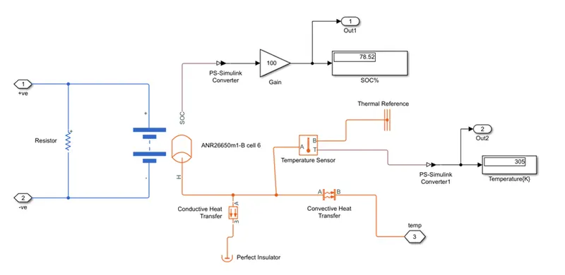
- In this module we used the table based battery block in which we put the datasheet value on it.here i put the battery specification like, 2.5Ah capacity,initial temp.value is 298K etc.and addition to that accross the battery terminal we use the 5 ohms resistor to show the this is the faulty cell.
- also here we use the conductive heat transfer block in which we put the thermal conductivity is 401 W/(K*m),area is 10 m^2,and thickness is 0.1m.
- here we use the convective heat transfer block in which we put the heat transfer co-efficients is 20 W/(K*m^2),area is 50 m^2.and one end of this block is connected to thermal source and other is connected to perticular cell.
- here we use perfect insulator also.
- here we use temperature sensor to sense the temperature of cell and display the value in scope and dashboard.also it one end connected to thermal referance.
- and SOC of every cell is also calculate by using add and gain block,and display the soc value in % in display block.
Module 3 [Cell 7-10]:
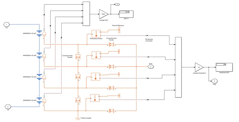
- In this module we used the 4 table based battery block in which we put the datasheet value on it.here i put the battery specification like, 2.5Ah capacity,initial temp.value is 298K etc.and this 4 cell are connected in series.
- also here we use the conductive heat transfer block in which we put the thermal conductivity is 401 W/(K*m),area is 10 m^2,and thickness is 0.1m.
- here we use the convective heat transfer block in which we put the heat transfer co-efficients is 20 W/(K*m^2),area is 10 m^2.and one end of this block is connected to thermal source and other is connected to perticular cell.
- here we use perfect insulator also.
- here we use temperature sensor to sense the temperature of cell and display the value in scope and dashboard.also it one end connected to thermal referance.
- and SOC of every cell is also calculate by using add and gain block,and display the soc value in % in display block.
SOC Calculation Model:
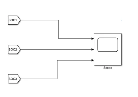
- here we use the 3 goto block and 3 from block and scope to analyze the change in soc of 3 different cell module.
Temperature Calculation Model:
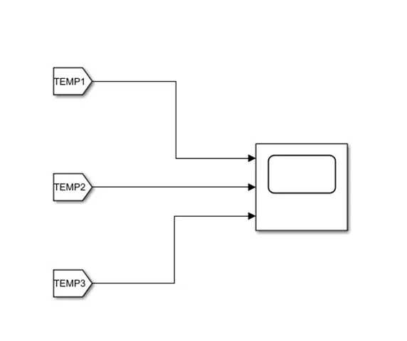
- here we use the 3 goto block and 3 from block and scope to analyze the change in temperature of 3 different cell module.
To incorporate for the positioning of this cell(center of pack) certain changes have been made:
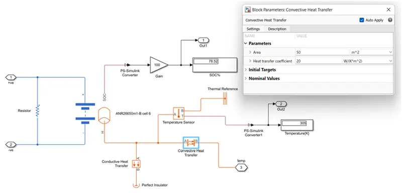
- the convective area is 10 m^2 for the remaining 9 cell,but has been increased to 50m^2 here.
- the ambient temperature provided from temperature source to the ramaining 9 cell are the same 298K,but has an increament of 7K for this cell.its means 305K.
Result:
A] At 25oC:
1] SOC OF Different Module [%]:
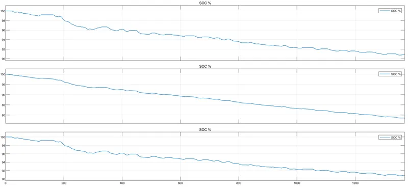
- model 2 has a much steeper slope than the others bcoz of added 5 ohmc resistor.a load(in the form of resistor) with a resistance of just 5 ohms will draw in more current compared to no added load.wich means greater rate of discharge and hence more drainage of SOC.
2] Temperature Change In Module [K]:
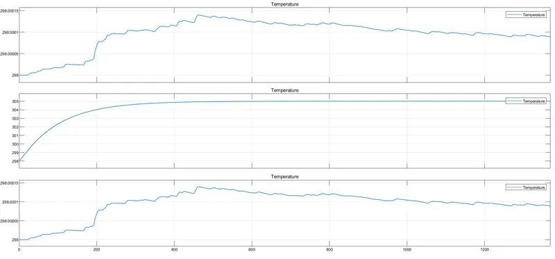
- Initial temperatre of batery pack is set to 298K.
- much steeper rise in temperature of module 2 compared to other module due to increased surface area contact and its position being in the center of the battery pack.
- although ambient temperature supplied is 298K,module 2 reaches 305K (while the other cell are at 298K) for the aforementioned two reasons in addition to the fact that there is also added 5ohms resistance in mode 2.
3] Dashboard for Indication of SOC and Temperature Change:
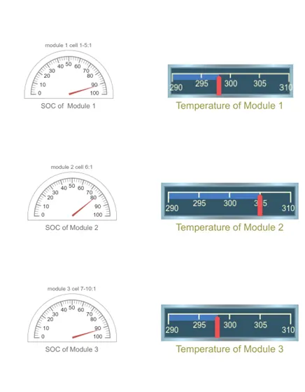
- both the gauge showing the change in SOC and change in Temperature.
B] At 45oC:
1] SOC OF Different Module [%]:
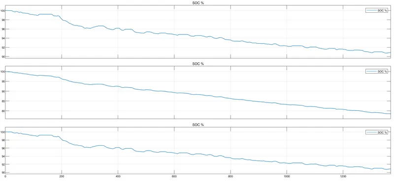
- model 2 has a much steeper slope than the others bcoz of added 5 ohmc resistor.a load(in the form of resistor) with a resistance of just 5 ohms will draw in more current compared to no added load.wich means greater rate of discharge and hence more drainage of SOC.
2] Temperature Change In Module [K]:
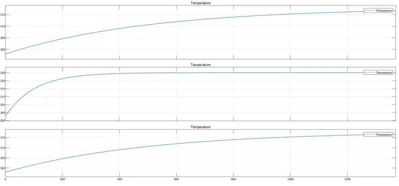
- Initial temperatre of batery pack is set to 298K.
- much steeper rise in temperature of module 2 compared to other module due to increased surface area contact and its position being in the center of the battery pack.
- although ambient temperature supplied is 318K,module 2 reaches 325K (while the other cell are at 318K) for the aforementioned two reasons in addition to the fact that there is also added 5ohms resistance in mode 2
3] Dashboard for Indication of SOC and Temperature Change:
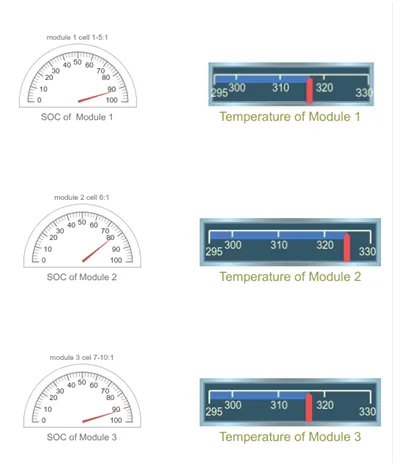
- both the gauge showing the change in SOC and change in Temperature.
C] At -10oC:
1] SOC OF Different Module [%]:
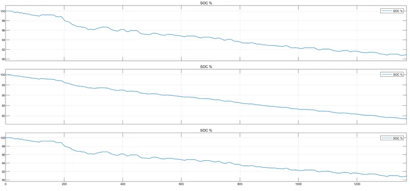
- model 2 has a much steeper slope than the others bcoz of added 5 ohmc resistor.a load(in the form of resistor) with a resistance of just 5 ohms will draw in more current compared to no added load.wich means greater rate of discharge and hence more drainage of SOC.
2] Temperature Change In Module [K]:
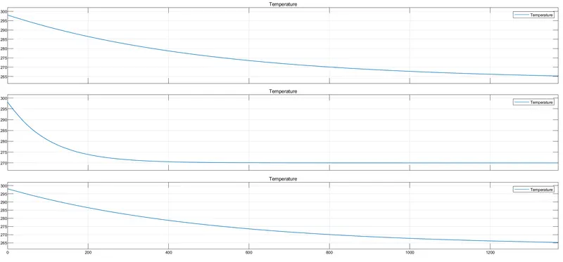
- Initial temperatre of batery pack is set to 298K.
- much steeper fall in temperature of module 2 compared to other module due to increased surface area contact and its position being in the center of the battery pack.
- although ambient temperature supplied is 263K,module 2 reaches 270K (while the other cell are at 263K) for the aforementioned two reasons in addition to the fact that there is also added 5ohms resistance in mode 2
3] Dashboard for Indication of SOC and Temperature Change:
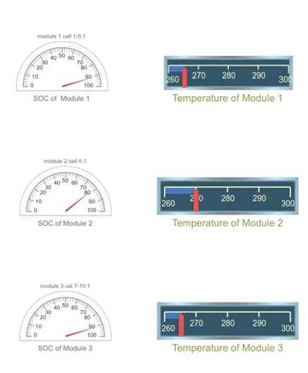
- both the gauge showing the change in SOC and change in Temperature.
Conclusion:
From this different case study I conclude that:
- When we ambient temperature increases then obviously cell temperature is increased also this ambient temperature adverse effect reflects on the age of the battery pack and vice versa.
- Similarly when we decrease C rate then shows the favorable and unfavorable effects on the age, SOC, temperature and voltage of the battery pack.
- The age of the battery increases slowly, SOC not able to charge or discharge completely, cell temperature is less and in the voltages spikes are present.