Week -2
AIM: This challenge aims to make a simulink model of a doorbell using a soleniod block and make another simulink model where a thermistor will be used to sense to the temperuture of a heater & turn it on or turn it off the fan.
OBJECTIVE:
- Make a Simulink model of Doorbell using solenoid block with the following details:
In the above arrangement, when the switch is closed the electromagnet receives electrical power from the battery and pulls the metal arm to hit the bell producing sound.
Create a situation where the switch is closed for 2 seconds and then released. Observe the physical movement of the plunger.
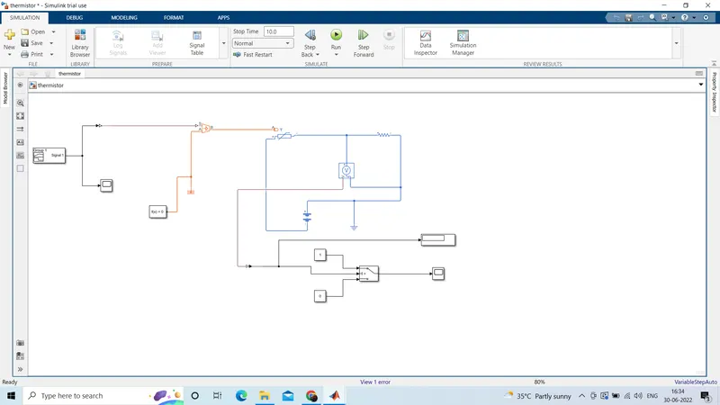
2. Use a thermistor to sense the temperature of a heater & turn on or turn off the fan as per the below conditions:
Temperature source: 20 °C from 0 to 10 seconds,
27 °C from 10 to 30 seconds,
23 °C from 30 to 50 seconds,
Fan conditions: ON if the temperature above 25 °C, OFF otherwise
SOLUTION OF OBJECTIVE-1:
THEORY:
DOORBELL:
A doorbell is a signaling device typically placed near a door to a building's entrance. When a visitor presses a button the bell rings inside the building, alerting the occupant to the presence of the visitor. the heart of a doorbell is an electromagnet. electromagnets are coils of wire wrapped around a small piece of magnetic metal.
when electricity passes through the wire, it creates a magnetic field around the wire.when you press a doorbell button,you complete an electrical circuit that allows household electricity to flow through the doorbell's internet electromagnet.the magnetic field generated by the electromagnet is then used to power a mechanism that creates the doorbell sound.
Doorbells are low-voltage devices. This means they require relatively little energy to operate. An important part of a doorbell mechanism is the transformer. the transformer converts regular 120-volts household current to the lower voltage (usually somewhere between 6-16 volts) required by the doorbell.
SOLENIOD:
A soleniod is a 3-dimensional structure of wire. when this wire is wrapped around a metallic block in a coil and electricity is passed through it, it was some.Solenoids provide magnetic focusing of electrons in vacuums, notably in television camera tubes such as vidicons and image orthicons. Electrons take helical paths within the magnetic field. These solenoids, focus coils, surround nearly the whole length of the tube.the side in which the current appears to be passing clockwise is the southpole, and the side in which the current seems to be passing anticlockwise is the northern pole. the soleniod works just like a bar magnet and therefore has many uses. This principle is used to create values, among other things. where the soleniod operates an electirc switch ,it is a relay.
FIG 2: traditional doorbell
simulink model of objective-1:
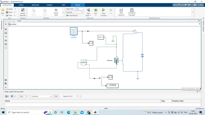
FIG3: simulink model of objective-1
The figure above is the representation of "A doorbell operated on soleniod".In this model, some blocks are used to make the working model of the doorbell.These blocks are:
1.Pulse Generator: The pulse generator block generates square wave pulses at regular intervals. The block waveform parameters, Amplitude, pulse width, period,and phase delay, determine the shape of the output waveform.
2.Simulink-PS converter: converts the unitless simulink input signal to a physical signal.
3.scope:Display signals generated during simulation.
4.switch:switch controlled by an external physical signal.
5.Battery: The battery block represents a simple battery model.
6.Soleniod:Model electrical characteristics and generated force of soleniod.
7.ideal transiational motion sensor:The Ideal Translational Motion Sensor block represents a device that converts an across variable measured between two mechanical translational nodes into a control signal proportional to velocity or position. You can specify the initial position (offset) as a block parameter.The sensor is ideal since it does not account for inertia, friction, delays, energy consumption, and so on.Connections R and C are mechanical translational conserving ports that connect the block to the nodes whose motion is being monitored. Connections V and P are physical signal output ports for velocity and position, respectively.
The block positive direction is from port R to port C. This means that the velocity is measured as v = vR – vC, where vR, vC are the absolute velocities at ports R and C, respectively.
8.Mechanical transiational reference: The Mechanical Translational Reference block represents a reference point, or frame, for all mechanical translational ports. All translational ports that are rigidly clamped to the frame (ground) must be connected to a Mechanical Translational Reference block.
9.Electrical reference:The Electrical Reference block represents an electrical ground. Electrical conserving ports of all the blocks that are directly connected to ground must be connected to an Electrical Reference block. A model with electrical elements must contain at least one Electrical Reference block.
10.solver configuration:Physical network environment and solver configurationEach physical network represented by a connected Simscape block diagram requires solver settings information for simulation.
11.ps-simulink converter: convert physical signal into simulink output signal.
MODEL EXPLANATION:
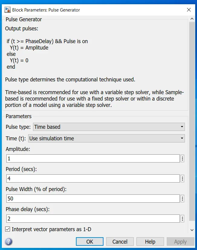
- The pulse generator is used to give the signal input where,Amplitude=1,period=4sec,pulse width=50%,and phase delay=2sec.(see fig4).
- After that, the inputs signal is converted into physical form with the use of "simulink-ps converter" and further send to the switch of the electrical circuit.
- The electrical circuit consists of a soleniod, a battery,and a switch. one end is connected to the battery and its other end is connected to the battery and its other end is connected to the switch.An electrical reference is provided in the electrical circuit.
- The mechanical part of the soleniod is connected to an ideal translation motion sensor and mechanical translational reference.
- The p-port of the sensor makes a connections with the "ps-simulink converter" to provide the output in signal form.furture, the converter is connected with scope to display our output signal.
6.A solver configuration is connected to an electrical circuit to solve all parameters before the beginning of the simulation.
OUTPUT:
Here we can see that the switch is closed for 2 seconds and after that switch is open.Amplitude=0 means the switch is closed. it can also be seen that the plunger strikes after every 2 second.
The motion of the plunger was simulated and recorded and plotted in scope.
solution of objective-2:
THEORY:
Thermistors are a type of semiconductor, meaning they have greater resistance than conducting materials, but lower resistance than insulating materials. The relationship between a thermistor’s temperature and its resistance is highly dependent upon the materials from which it’s composed. The manufacturer typically determines this property with a high degree of accuracy, as this is the primary characteristic of interest to thermistor buyers.
Thermistors are made up of metallic oxides, binders and stabilizers, pressed into wafers and then cut to chip size, left in disc form, or made into another shape. The precise ratio of the composite materials governs their resistance/temperature “curve.” Manufacturers typically control this ratio with great accuracy, since it determines how the thermistor will function.
A thermistor is a type of resistor whose resistance is strongly dependent on temperature, more so than in standard resistors. The word thermistor is a portmanteau of thermal and resistor.Thermistors are divided based on their conduction model. Negative Temperature Coefficient (NTC) thermistors have less resistance at higher temperatures, while Positive Temperature Coefficient (PTC) thermistors have more resistance at higher temperatures.[1] Hence, a PTC thermistor's resistance is directly proportional to temperature.
Simulink model of objective-2:
Temperature source: 20 °C from 0 to 10 seconds,
27 °C from 10 to 30 seconds,
23 °C from 30 to 50 seconds,
Fan conditions: ON if the temperature above 25 °C, OFF otherwise