Project 2 Thermal modeling of battery pack
AIM;
TO create model for 10 cell series lithium ion battery model, simulate the thermal effects and compare life cycle performance at various temperatures, charge & discharge rates using MATLAB.
THEORY;
Lithium-ion batteries power the lives of millions of people each day. From laptops and cell phones to hybrids and electric cars, this technology is growing in popularity due to its light weight, high energy density, and ability to recharge.
So how does it work?
This animation walks you through the process.
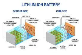
THE BASICS
A battery is made up of an anode, cathode, separator, electrolyte, and two current collectors (positive and negative). The anode and cathode store the lithium. The electrolyte carries positively charged lithium ions from the anode to the cathode and vice versa through the separator. The movement of the lithium ions creates free electrons in the anode which creates a charge at the positive current collector. The electrical current then flows from the current collector through a device being powered (cell phone, computer, etc.) to the negative current collector. The separator blocks the flow of electrons inside the battery.
CHARGE/DISCHARGE
While the battery is discharging and providing an electric current, the anode releases lithium ions to the cathode, generating a flow of electrons from one side to the other. When plugging in the device, the opposite happens: Lithium ions are released by the cathode and received by the anode.
ENERGY DENSITY VS. POWER DENSITY
The two most common concepts associated with batteries are energy density and power density. Energy density is measured in watt-hours per kilogram (Wh/kg) and is the amount of energy the battery can store with respect to its mass. Power density is measured in watts per kilogram (W/kg) and is the amount of power that can be generated by the battery with respect to its mass. To draw a clearer picture, think of draining a pool. Energy density is similar to the size of the pool, while power density is comparable to draining the pool as quickly as possible.
Series Connections
Series connections involve connecting 2 or more batteries together to increase the voltage of the battery system but keeps the same amp-hour rating. Keep in mind in series connections each battery needs to have the same voltage and capacity rating, or you can end up damaging the battery. To connect batteries in series, you connect the positive terminal of one battery to the negative of another until the desired voltage is achieved. When charging batteries in series, you need to utilize a charger that matches the system voltage. We recommend you charge each battery individually, with a multi-bank charger, to avoid an imbalance between batteries.
In the image below, there are two 12V batteries connected in series which turns this battery bank into a 24V system. You can also see that the bank still has a total capacity rating of 100 Ah.
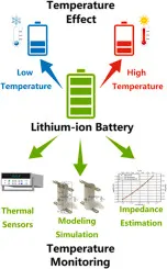
Temperature effect and thermal impact in lithium-ion batteries;
Lithium-ion batteries (LIBs), with high energy density and power density, exhibit good performance in many different areas. The performance of LIBs, however, is still limited by the impact of temperature. The acceptable temperature region for LIBs normally is −20 °C ~ 60 °C. Both low temperature and high temperature that are outside of this region will lead to degradation of performance and irreversible damages, such as lithium plating and thermal runaway. Therefore, understanding the temperature effects and accurate measurement of temperature inside lithium-ion batteries are important for the proper battery management. The state-of-art achievements in monitoring the temperature inside the LIBs can be divided into contact measurement and contactless measurement. This review overviews recent development in both the understanding of the temperature effects and the temperature monitoring, and discusses the challenges and possible future directions in achieving optimum battery performance.
10 CELL SERIES LITHIUM ION BATTERY MODEL;
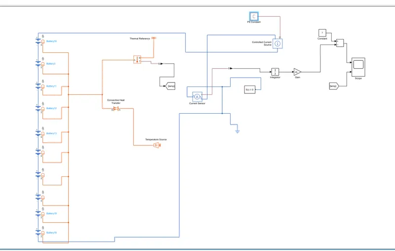
BLOCK USED;
Convective Heat Transfer

The Convective Heat Transfer block represents a heat transfer by convection between two bodies by means of fluid motion. The transfer is governed by the Newton law of cooling:
Q=k⋅A⋅(TA−TB),
where:
-
Q is heat flow.
-
k is convection heat transfer coefficient.
-
A is surface area.
-
D is distance between layers (that is, thickness of material).
-
TA and TB are temperatures of the two bodies.
Connections A and B are thermal conserving ports associated with the points between which the heat transfer by convection takes place. The block positive direction is from port A to port B. This means that the heat flow is positive if it flows from A to B.
Current Sensor

The Current Sensor block represents an ideal current sensor, that is, a device that converts current measured in any electrical branch into a physical signal proportional to the current.
Use the + and - ports to connect the sensor in series with the other blocks in the branch where you want to measure the current. Port I outputs the measurement result as a physical signal. Use a PS-Simulink Converter block to connect this port to Simulink® blocks, such as Scope or Display.
Controlled Current Source

The Controlled Current Source block converts the Simulink® input signal into an equivalent current source. The generated current is driven by the input signal of the block. The positive current direction is as shown by the arrow in the block icon.
You can initialize the Controlled Current Source block with a specific AC or DC current. If you want to start the simulation in steady state, the block input must be connected to a signal starting as a sinusoidal or DC waveform corresponding to the initial values.
Temperature Source

The Temperature Source block represents an ideal source of thermal energy that is powerful enough to maintain specified temperature at its outlet regardless of the heat flow consumed by the system.
The source generates constant absolute temperature, defined by the Temperature parameter value.
Temperature Sensor

The Temperature Sensor block represents an ideal temperature sensor, that is, a device that determines the temperature differential measured between two points without drawing any heat.
Connections A and B are thermal conserving ports that connect to the two points where temperature is being monitored. Port T is a physical signal port that outputs the temperature differential value.
The block positive direction is from port A to port B. The measured temperature is determined as T = TA – TB.
Integrator

The Integrator block outputs the value of the integral of its input signal with respect to time.
{˙x(t)y(t)=u(t)=x(t) x(t0)=x0
where:
-
u is the block input.
-
y is the block output.
-
x is the block state.
-
x0 is the initial condition of x.
While these equations define an exact relationship in continuous time, Simulink uses numerical approximation methods to evaluate them with finite precision. Simulink can use several different numerical integration methods to compute the output of the block, each with advantages in particular applications. Use the Solver pane of the Configuration Parameters dialog box (see Solver Pane) to select the technique best suited to your application.
The selected solver computes the output of the Integrator block at the current time step, using the current input value and the value of the state at the previous time step. To support this computational model, the Integrator block saves its output at the current time step for use by the solver to compute its output at the next time step. The block also provides the solver with an initial condition for use in computing the block's initial state at the beginning of a simulation. The default value of the initial condition is 0. Use the block parameter dialog box to specify another value for the initial condition or create an initial value input port on the block.
Gain

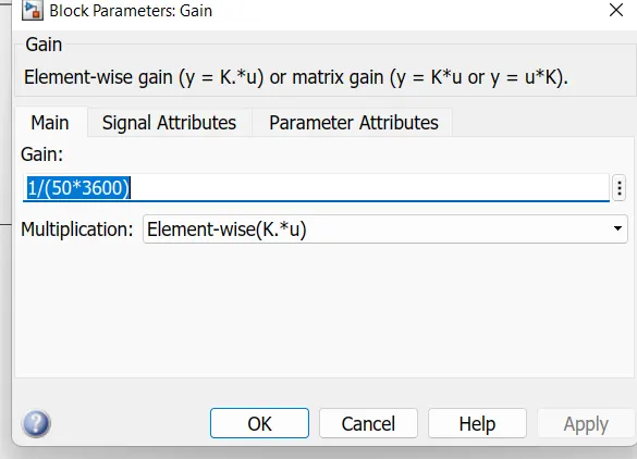
The Gain block multiplies the input by a constant value (gain). The input and the gain can each be a scalar, vector, or matrix.
You specify the value of gain in the Gain parameter. The Multiplication parameter lets you specify element-wise or matrix multiplication. For matrix multiplication, this parameter also lets you indicate the order of the multiplicands.
Gain is converted from doubles to the data type specified in the block mask offline using round-to-nearest and saturation. The input and gain are then multiplied, and the result is converted to the output data type using the specified rounding and overflow modes.
PS CONSTANT;

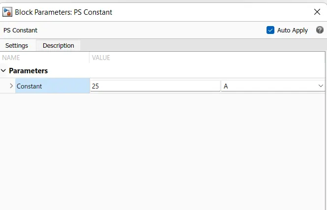
The PS Constant block generates a physical signal of a constant value. You specify the value and unit of the signal as the Constant parameter.
RESULT;
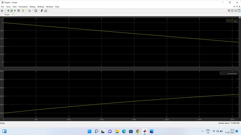
Hear the stop time is 3600 we give 25A in ps constant the soc is 50 pecentage and the temperature is higher 410k