Project 2 Thermal modeling of battery pack
Lithium ion battery:
Electric and hybrid vehicle may present the most promising solution for pollution problems caused by
the emission of conventional internal combustion engine. These technologies will highly depend on
battery packs. The role of battery as the power source in electric drive vehicle is important. Due to the
high energy density, Lithium-ion batteries have gained much attention as a viable candidate to
increase vehicle range and performance of electric drive vehicle application. However, there is a
variety of thermal limitations for Lithium-ion battery.
Lithium-ion batteries are commonly used for portable electronics and electric vehicles and are growing in popularity for military and aerospace applications.
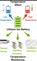
Temperature is known to have a significant impact on the performance, safety and cycle lifetime of lithium-ion batteries (LiB).
The temperature of a Lithium Ion battery is very important for its performance, capacity, safety and it is influenced by environmental temperature and discharging and charging process. Therefore I built up a thermal model of battery in order to calculate and estimate the cell temperature.
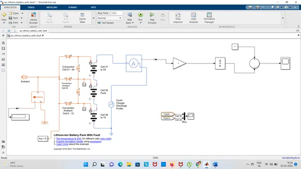
For 10 cell series connection I used lithium ion battery using MATLAB & SIMULINK for finding thermal effect and life cycle performance related to temperature, charge & discharge.
Here it is showing that fault is introduced into one of the cells to see the impact on the battery performance. The fault is represented by charging the parameters for the cell 5 fault subsystem reducing the capacity ,OCV, increasing the resistance value.
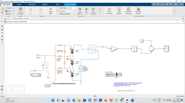
to simulate a battery pack consisting of multiple series-connected cells in an efficient manner. It also shows how a fault can be introduced into one of the cells to see the impact on battery performance and cell temperatures. For efficiency, identical series-connected cells are not just simply modeled by connecting cell models in series. Instead a single cell is used, and the terminal voltage scaled up by the number of cells. The fault is represented by changing the parameters for the Cell 10 Fault subsystem, reducing both capacity and open-circuit voltage, and increasing the resistance values.
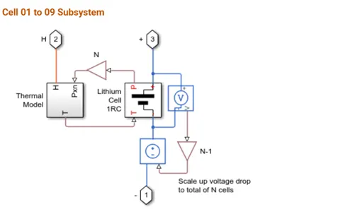
Cell 1 to 9 subsystem:
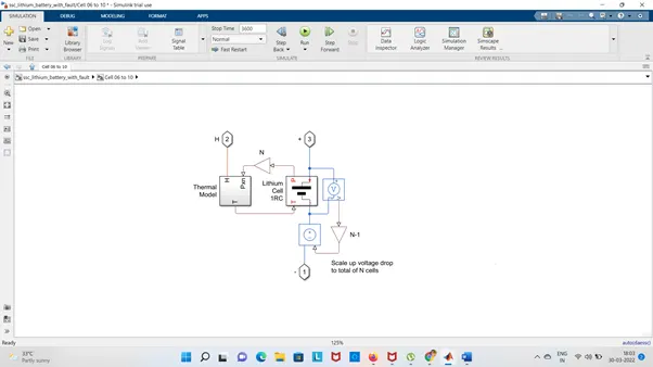
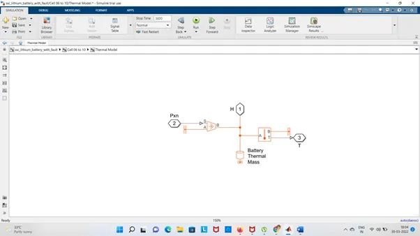
The cell subsystem is basically Thermal model to calculate the temperature and thermal effect of the cells and for the battery pack.
The voltage sensor block is used to covert voltage measured between any electrical connections into a physical signal proportional to the voltage.
Current voltage source is represents an ideal voltage source that is maintain the specified voltage and the output voltage.
Using PS Gain block: This block multiplies the input physical signal by a constant:
y = u .* gain
The Gain parameter accepts both positive and negative values. All connections are physical signal ports.
Cell 6 to 10:
Thermal Model:
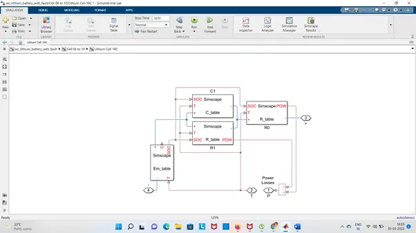
Lithium cell 1RC Subsystem:
The block basically consists of capacitance value which depends upon an external physical signal input SOC and T.
The capacitance value is varying with time T.
Resistance value which is depends upon an external physical signal SOC & T
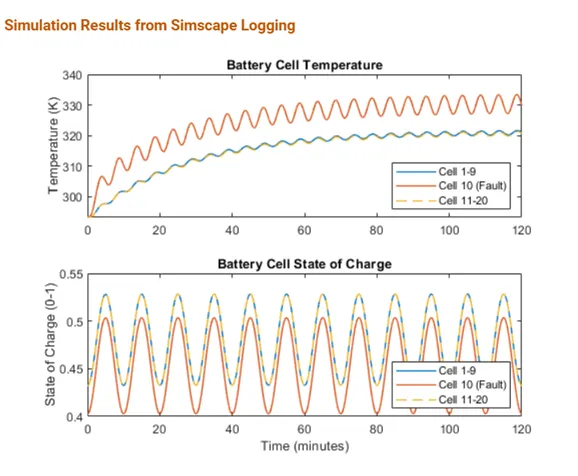
Results in Scope:
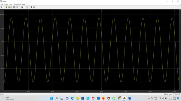
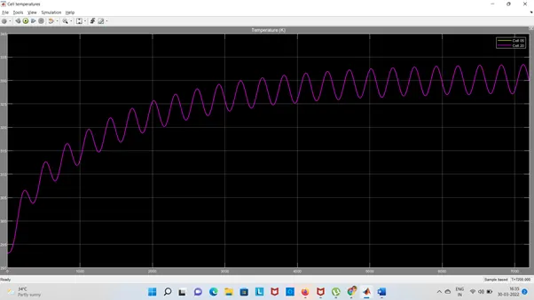
Used Block to make the Simulations:

This block models heat transfer in a thermal network by convection due to fluid motion. The rate of heat transfer is proportional to the temperature difference, heat transfer coefficient, and surface area in contact with the fluid.
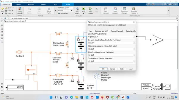
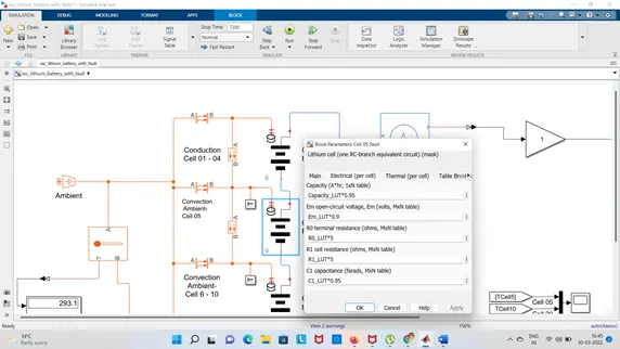
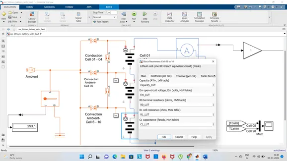
Thermal behaviour & fault set up: Lithium Ion cell one RC- Branch equivalent circuit details of 10cells.
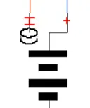
Cell 1 to 4: connected cell are 4
Temp is 299K
Current Sensor:
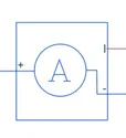
The block represents an ideal current sensor, that is, a device that converts current measured in any electrical branch into a physical signal proportional to the current.
Connections + and - are conserving electrical ports through which the sensor is inserted into the circuit. Connection I is a physical signal port that outputs current value.
Display:
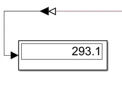
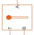
Temperature Sensor: This block measures temperature in a thermal network. There is no heat flow through the sensor. The physical signal port T reports the temperature difference across the sensor. The measurement is positive when the temperature at port A is greater than the temperature at port B.
Conductive Heat Transfer:
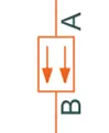
This block models heat transfer in a thermal network by conduction through a layer of material. The rate of heat transfer is governed by Fourier's law and is proportional to the temperature difference, material thermal conductivity, area normal to the heat flow direction, and inversely proportional to the layer thickness.
Thermal Reference:
This block represents a reference point in a thermal network where the temperature is equal to absolute zero

Electrical Reference: Electrical reference port. A model must contain at least one electrical reference port (electrical ground).
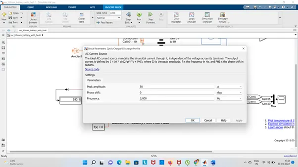
AC current source: The ideal AC current source maintains the sinusoidal current through it, independent of the voltage across its terminals. The output current is defined by I = I0 * sin(2*pi*f*t + PHI), where I0 is the peak amplitude, f is the frequency in Hz, and PHI is the phase shift in radians.
Results:
When the Temperatute is 299K
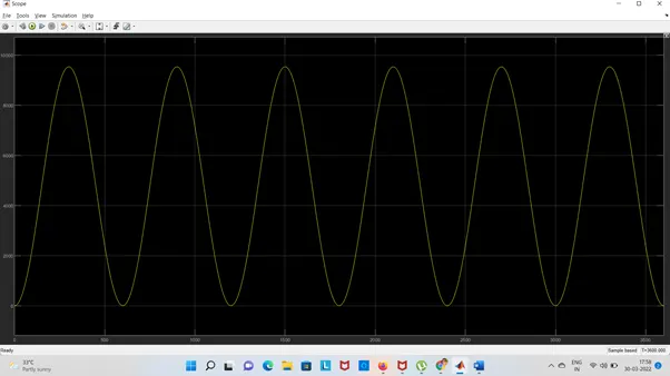
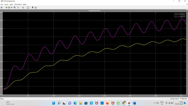
If Temperature is increased T = 315K
Results:
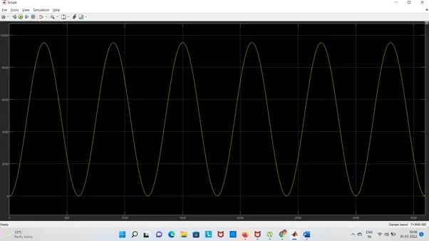
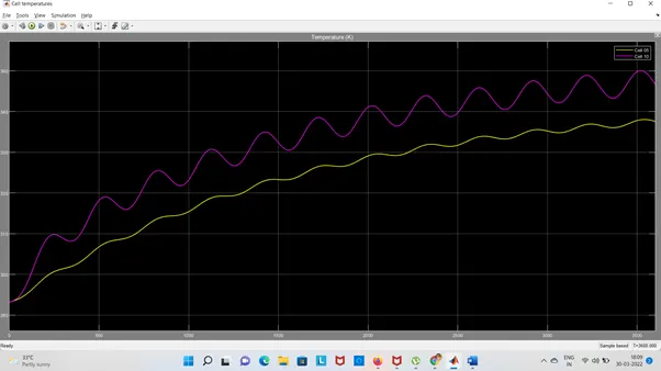
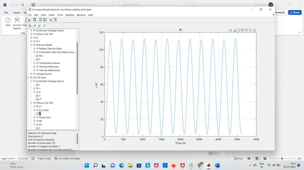
We can see that the temperature of cell no 5 is quickly fault.
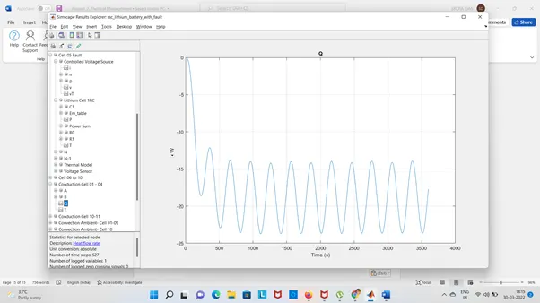
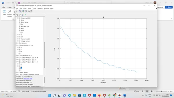
Heat flow rate & Temperature difference Graphs are shown below:
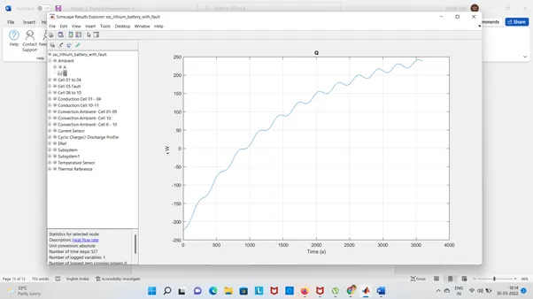
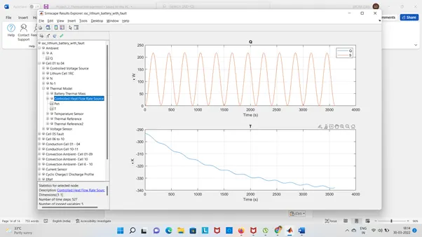
Fault in cell-5
Conduction of cell 1 to 4:
Convection of Cell 6 to 10:
Conclusion:
- Based on the Temperature changes the conduction & convection.
- State of charge (SOC) is same as any set of temperature.
- We can see the fault cell no 5 is fluctuating as compared to the other cell.