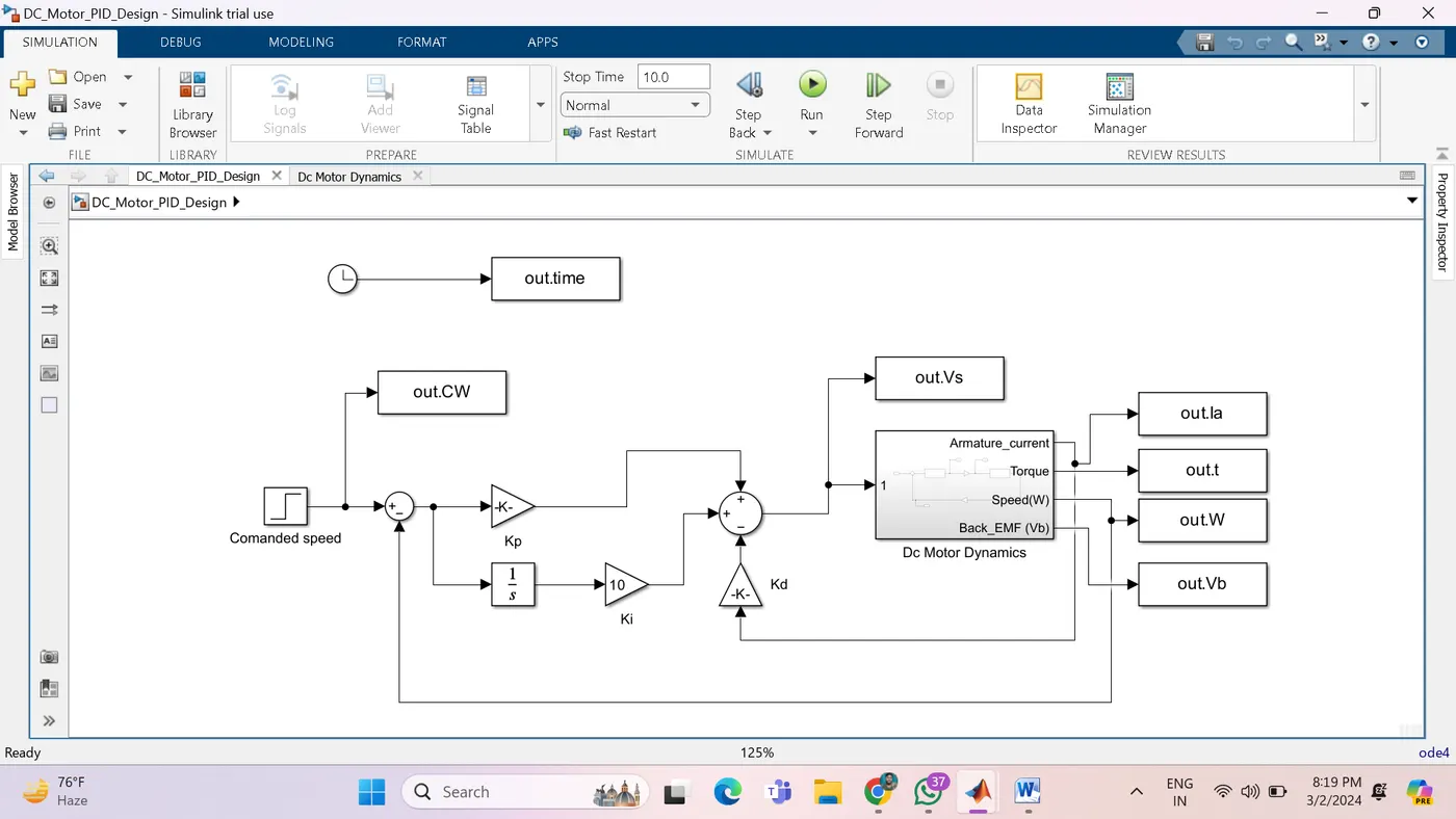
Project 2 - Speed Control of a Direct Current (DC) motor
The physical parameters for our example are:
Jm =0.01; % Moment of inertia of the rotor in kg-m^2Bm = 0.1; % Motor viscous friction constant in N-m-s
Km = 0.01; % Back EMF constant in v/rad/s
Kt = 0.01; % Motor torque constant in N-m/amp
Ra = 1.0; % Resistance of the motor circuit in ohmLa = 0.5; % Inductance of armature circuit in henries
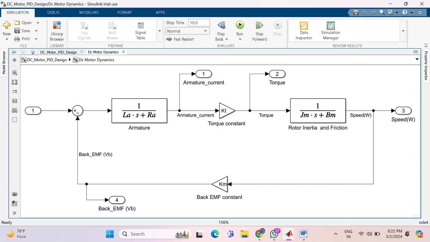
In general, the torque generated by a DC motor is proportional to the armature current and the strength of the magnetic field. In this example we will assume that the magnetic field is constant and, therefore, that the motor torque is proportional to only the armature current i by a constant factor Kt as shown in the equation below. This is referred to as an armature-controlled motor.
The back emf e is proportional to the angular velocity of the shaft by a constant factor Ke
Next we will apply Newton's law and Kirchoff's law to the motor system to generate the following equations:
(6)
%Load the Dc motor characteristic parameters
run Dc_motor_parameter.m
% PD design
% A = [-B/J Kt/J; -Km/La -Ra/La]
% B = [0;1/La];
A = [-Bm/Jm Kt/Jm; -Km/La -Ra/La];
B= [0;1/La];
fn=1.0;
wn = 2*pi*fn;
zeta = 0.5;
%desired pole
p1 = -zeta*wn+wn*sqrt(zeta^2-1);
p2 = -zeta*wn-wn*sqrt(zeta^2-1);
P = [p1;p2];
%pole placement design
K= place(A,B,P);
%Plot of model