Project 2 - Speed Control of a Direct Current (DC) motor
Speed Control of DC Motor Using PID Control
Aim - To regulate the speed of DC motor using PID Controller.
Abstract - This project presents a study on the implementation of a Proportional-Integral-Derivative (PID) control system for regulating the speed of a DC motor. The objective is to achieve precise and stable speed control by employing a PID controller, which combines proportional, integral, and derivative control actions to effectively adjust the motor's input voltage.
The control system design involves modeling the DC motor, tuning the PID controller parameters, and implementing the control algorithm in a microcontroller-based system. Simulation results using MATLAB/Simulink demonstrate the effectiveness of the PID control in maintaining the motor's speed under varying load conditions and disturbances.
The findings reveal that the PID control strategy exhibits superior performance in regulating the speed of the DC motor compared to traditional control methods. The results obtained from simulations and experiments validate the effectiveness and reliability of the proposed PID control system for precise speed control in DC motor applications.
Objectives-
1.) Obtaining the desired speed as per the speed command given.
2.) Reduction in overshoot, undershoot and other forms of disturbances.
Keywords - DC motor, PID control, speed regulation, simulation, control system design, MATLAB/Simulink.
Mathematical Modelling of DC Motor -
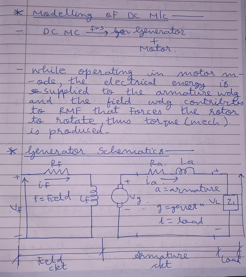
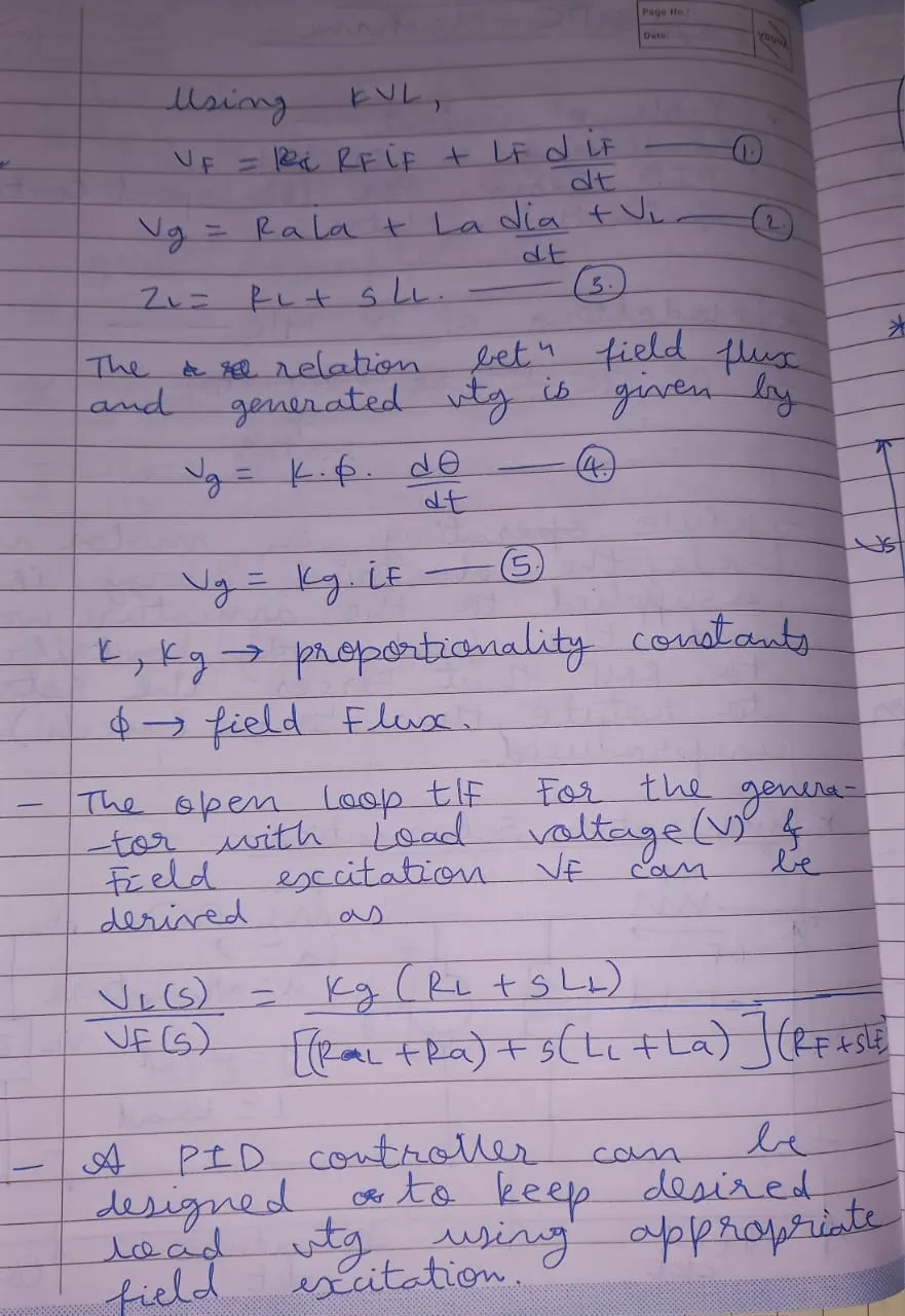
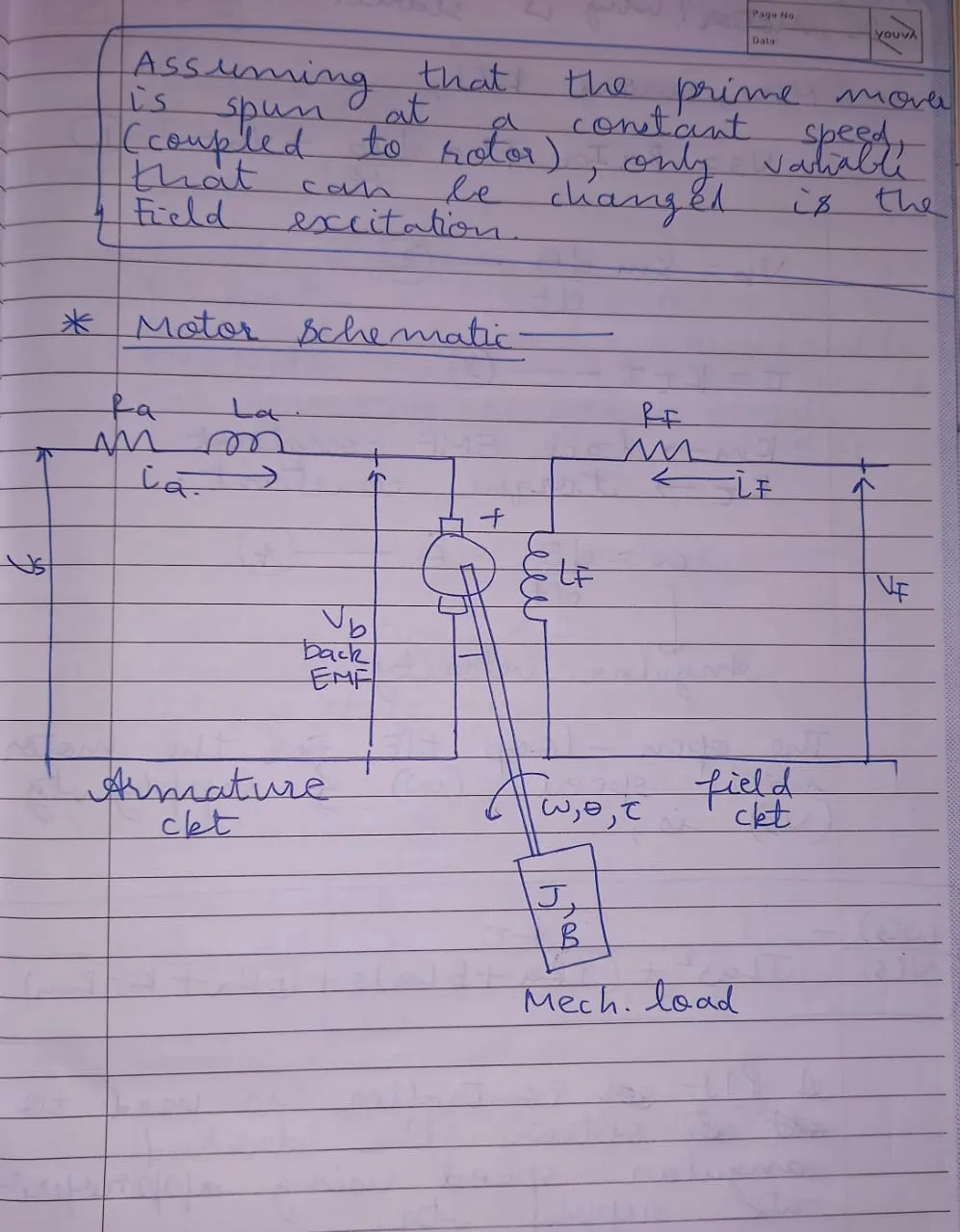
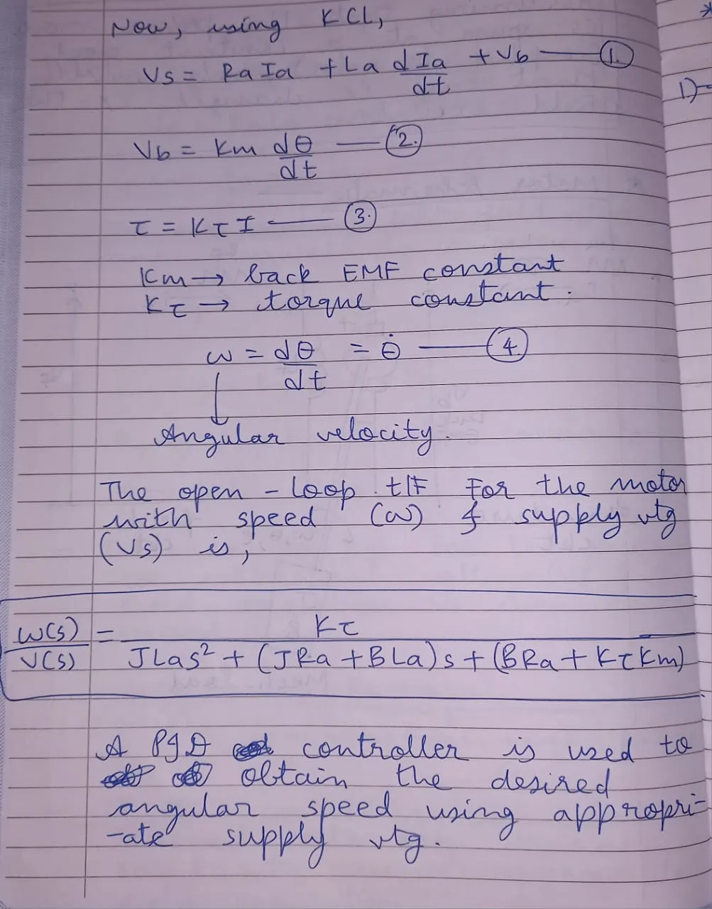
The mathematical model of a DC motor can be described by its electrical and mechanical components. A simple representation includes both electrical and mechanical equations.
Motor Parameters -
% This file contains the design parameters to model DC motor
Jm = 0.01; %MI of the rotor
Bm = 0.1 %motor viscous friction constant
Km = 0.01 % back emf constant
Kt = 0.01 %motor torque constant
Ra = 1 %armature circuit resistance
La = 0.5 %armature circuit inductance
% PD Design
% Plant Matrices
% A = [-Bm/Jm Kt/Jm; -Km/La Ra/La];
% B = [0; 1/La];
A = [-Bm/Jm Kt/Jm; -Km/La Ra/La];
B = [0; 1/La];
%Pole Placement Design
fn = 1;
wn = 2*pi*fn;
zeta = 0.5
%p1 = -zeta*wn+wn*sqrt(zeta^2-1);
%p2 = -zeta*wn-wn*sqrt(zeta^2-1);
p1 = -zeta*wn+wn*sqrt(zeta^2-1);
p2 = -zeta*wn-wn*sqrt(zeta^2-1);
P = [p1;p2];
K = place(A,B,P);
Simulations -
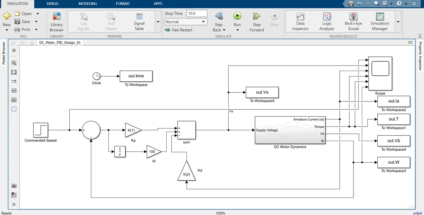
Fig. DC motor drive with PID control.
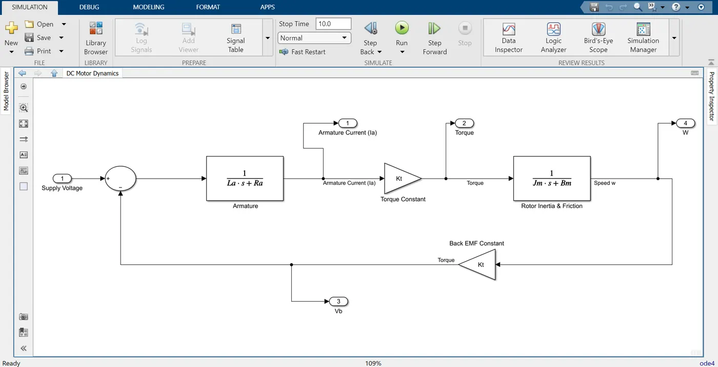
fig. DC motor model
Results -
Case 01 - A constant speed command of 5 rpm is applied.
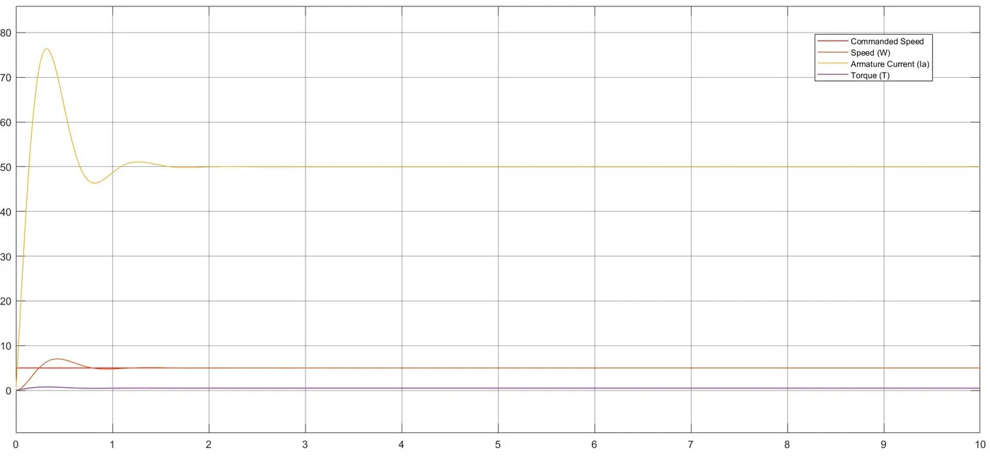
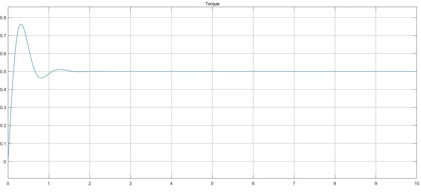
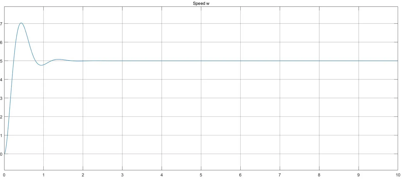
Case 02 - Speed accelarated to 5 rpm at instant of 5 seconds.
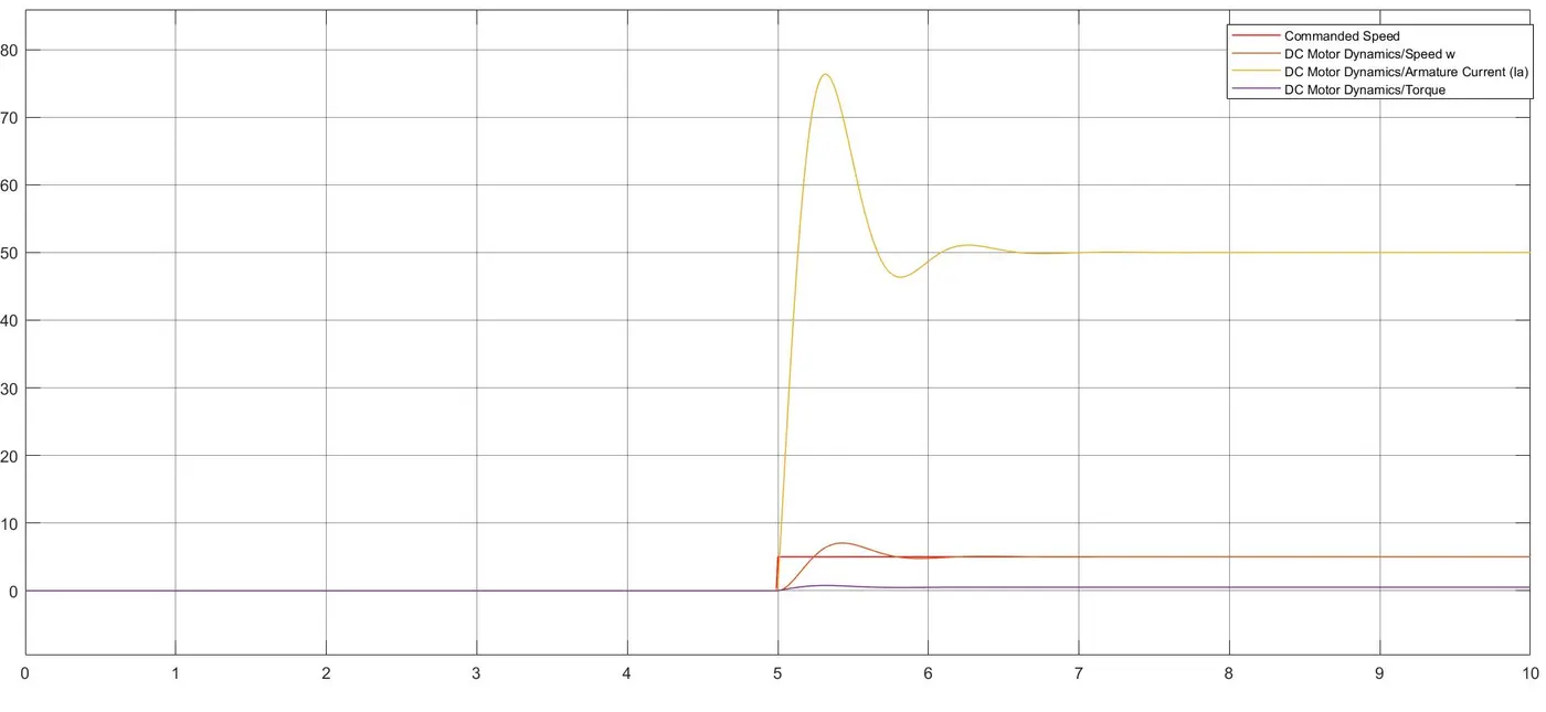
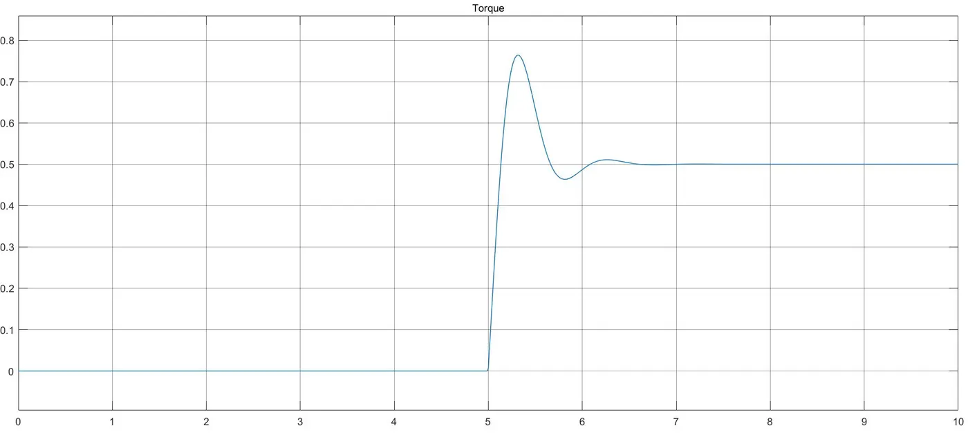
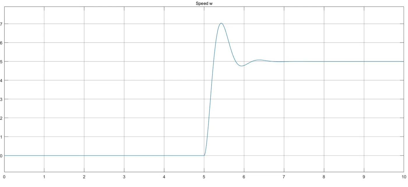
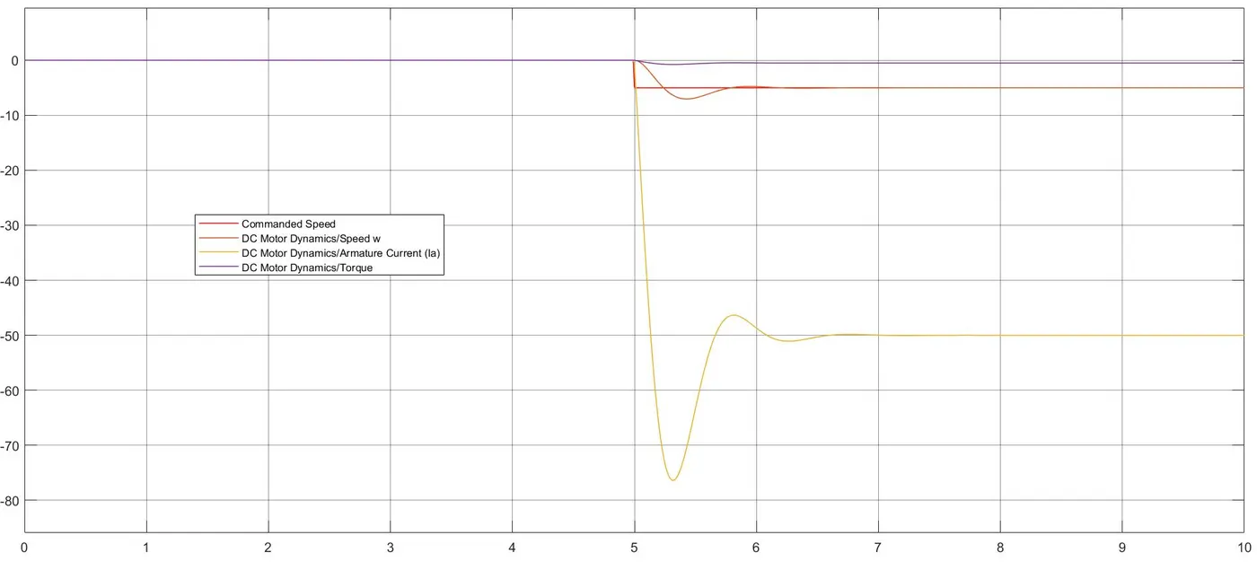
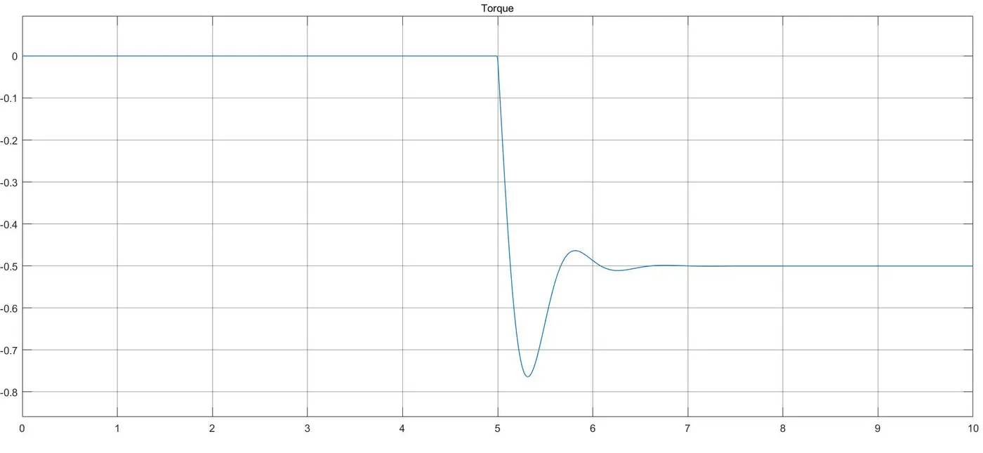
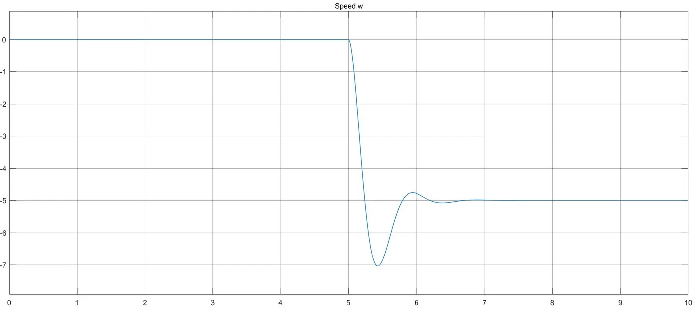
Case 03 - Speed reversal of - 5 rpm at instant of 5 seconds.
Conclusion -
Implementing a PID-based control system for a DC motor offers several advantages. It allows for precise regulation of motor speed and position (as per the given speed command as refernce), offering stability and accuracy in various applications. By effectively managing the Proportional, Integral, and Derivative components, this control scheme enables rapid response to disturbances, minimizes steady-state errors, and enhances overall system performance. However, successful implementation requires careful tuning of PID parameters to suit specific operating conditions. When appropriately configured, PID control can significantly improve motor efficiency, accuracy, and responsiveness, making it a valuable choice for diverse industrial and robotics applications.