Project 2 - Speed Control of a Direct Current (DC) motor
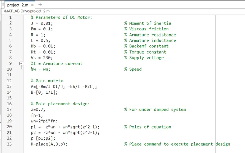
Parameters of DC Motor:
J = Moment of inertia
Bm = Viscous friction
R = Armature resistance
L = Armature inductance
Kb = Backemf constant
Kt = Torque constant
Vs = Supply voltage
Vb = Back emf voltage = Kb*w
I = Armature current
w=wn=speed
T = Motor Torque = Kt*I
State space representation of the DC motor:
X_dot = Ax +Bu ...................(1)
Y = Cx + Du ....................(2)
[w_dot; I_dot] = [-Bm/J Kt/J; -Kb/L -R/L][w; I] + [0; 1/L][V] .............(3)
Y(t) = [1 0][w; I] + [0][V] ..........................(4)
Comparing (1) and (2) with (3) and (4), we get,
A=[-Bm/J Kt/J; -Kb/L -R/L]
B=[0; 1/L]
Pole placement design:
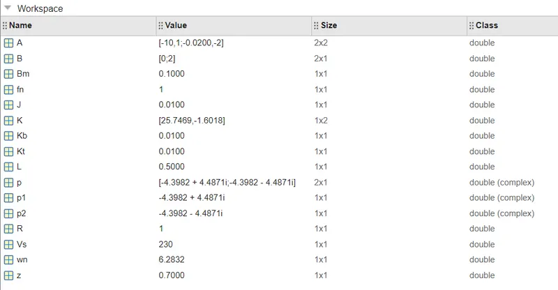
K=place(A,B,p)
K=[K1,K2]
K1 = Kp % Proportional gain
K2 = Kd % Derivative gain
Choose Ki = 0 initially % Integral gain
p=[p1;p2]
p1 = -z*wn + wn*sqrt(z^2-1)
p2 = -z*wn - wn*sqrt(z^2-1)
Choose z=0.7 for under damped system
fn=1
wn=2*pi*fn
PID controller design:
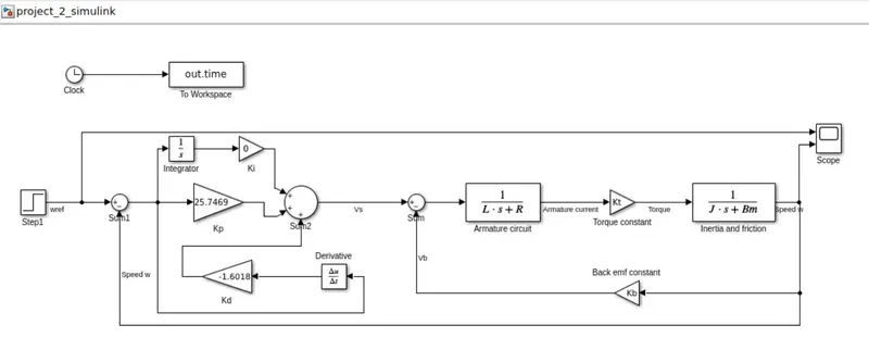
u(t) = Kp(xref - x1) + Ki*int(xref - x1)dt + Kd*d/dt*(xref - x1);
where
u(t) = control input
Kp=Proportional gain
Ki=Integral gain
Kd=Derivative gain
xref - x1 = error signal
xref = speed reference = wref
x1 = speed =w
Hence,
u(t) = Kp(wref - w) + Ki*int(wref -w)dt + Kd*d/dt*(wref-w);
1. Simulink model to simulate the design, Kp = 25.7469, Kd = -1.6018, Ki=0, Set speed wref = 30:
Simulink output:
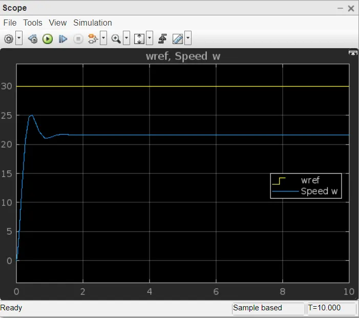
From the above output, PID design fails to track the set speed of 30 and had the actual speed of 22.
2. Simulink model to simulate the design, Kp = 25.7469, Kd = -1.6018, Ki designed to 55 from 0, Set speed wref = 30:
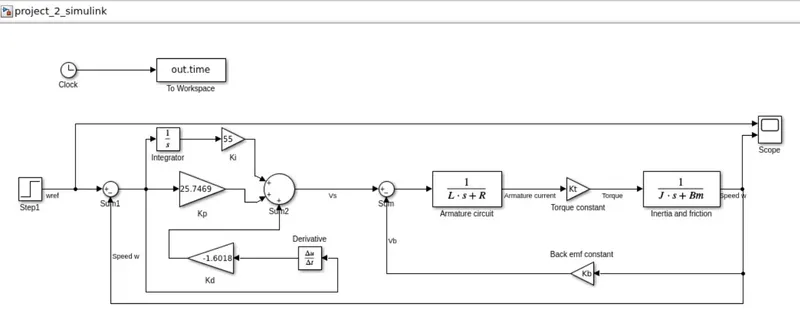
Simulink output:
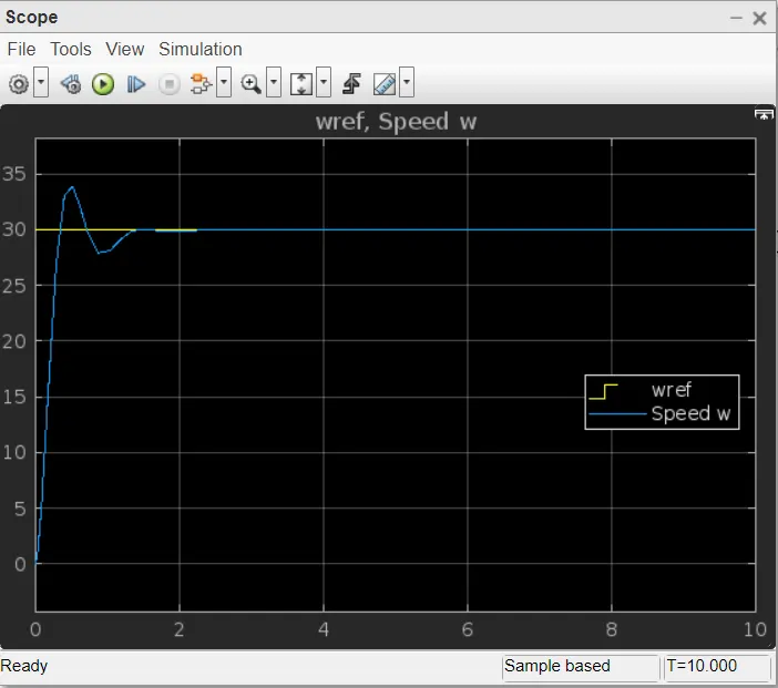
From the above output, PID design track the set speed of 30 with the actual speed and the design objectives like settling time, overshoot and steady state error are met.
3. Simulink model to simulate the design, Kp = 25.7469, Kd = -1.6018, Ki = 55, Set speed wref = 100:
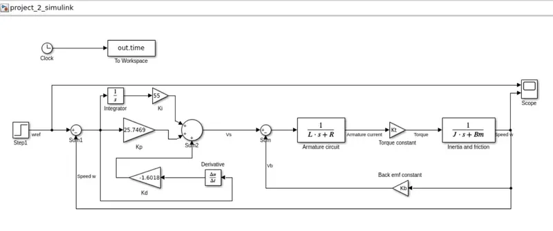
Simulink output:
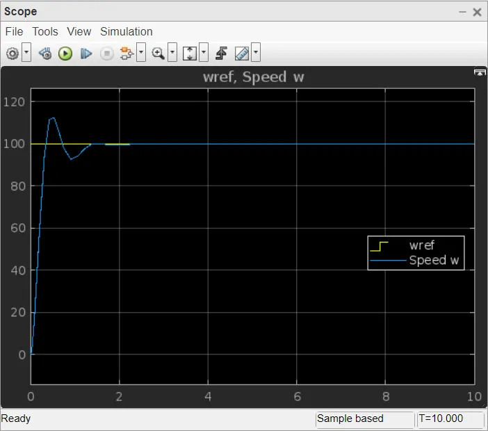
From the above output, PID design track the set speed of 100 with the actual speed and the design objectives like settling time, overshoot and steady state error are met.
If we change any one of the gain in the above PID gain set (Kp = 25.7469, Ki = 55, Kd = -1.6018), then the design will fail to track the set speed.