Project 2 - MODELLING, ANALYSIS & DESIGN OF COMPOSITE STUCTURES IN COMFLOR & ETABS
AIM:
To analyse and to design the composite high rise building uisng ETABS. And to design composite deck profile using comflor softare.
Flow Chart for composite high rise building analysis and design:
- Architectural plan study & Column shear wall position marking
- Steel beam alignment marking
- Material data & loading details from
- Comflor software or catelogue reference for deck design.
- Preparation of comflor deck design
- Calculation of weight of deck
- Story & Grid assignment in ETABS
- Materials, steel beam efinition, membrane definition , composite column definitions & concrete shear wall definition
- Load patterns, lateral load assignment , mass source , response spectrum, load combinations assignment
- Modelling of composite columns , shear walls , steel beams & membrane floors modelling
- Provision of loadings.
- Analysisng and designing the model. verifying all the members are passing the design
- Vibration analysis check with ETABS
- checking the deflections of composite beam & provision of pre-camber if required
Architectural Plan Study & column shear wall position making :
The peripheral yellow hatched column are positioned for gravity load resistance. The internal green color rc walls and lift area RC walls are planned for lateral load resistance. The column position & Rc wall alignment are sketched according to the partition wall layout, so that the element will get hidden.
PROCEDURE:
- Open ETABS new model
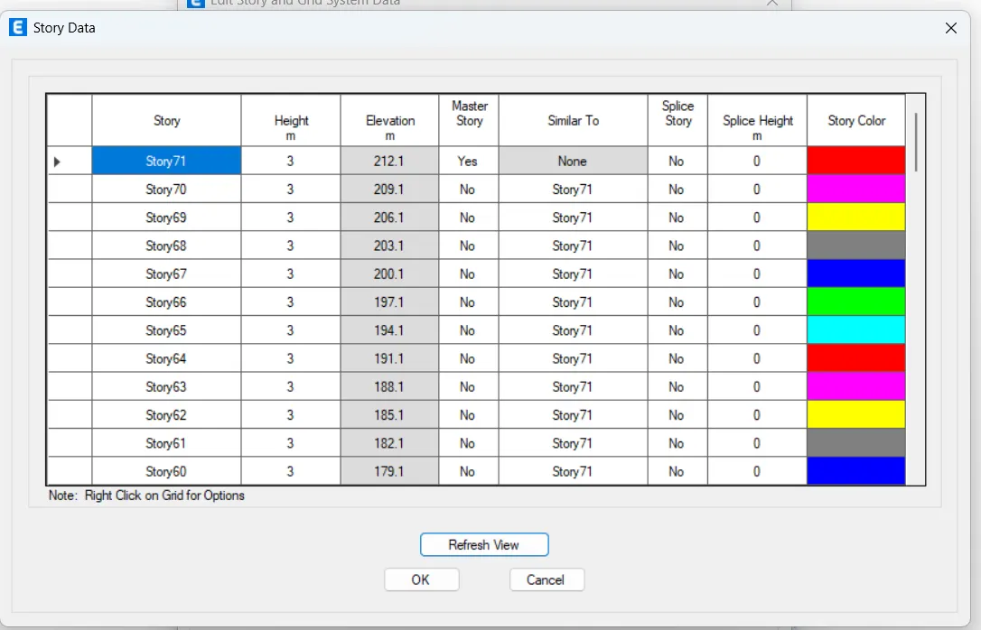
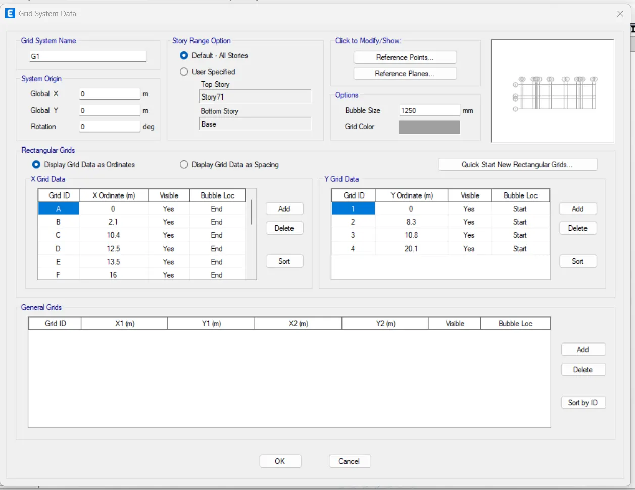
- select story & grids
Grids:
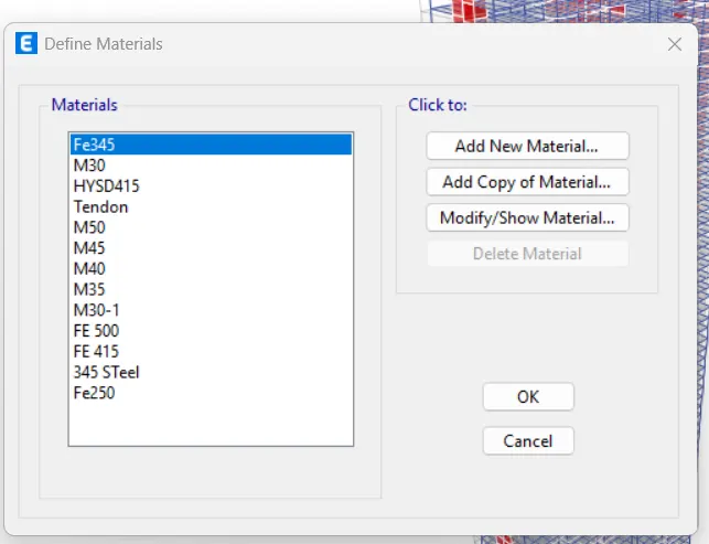
Material assignment :
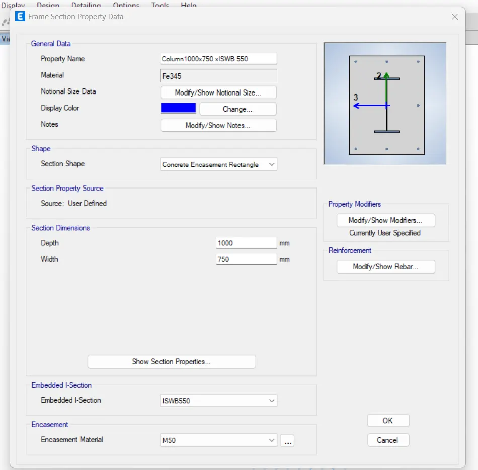
Composite column, Steel beam assignmenta:
Column:
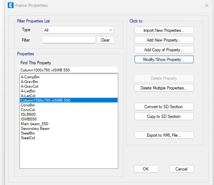
steel beam, primary and secondary beams:
Slab assignment equivalent to deck thickness:
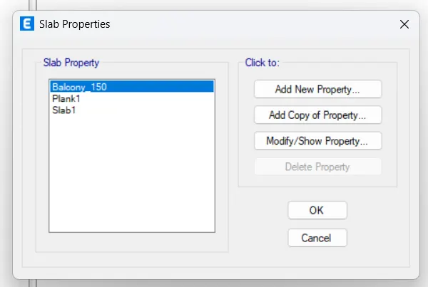
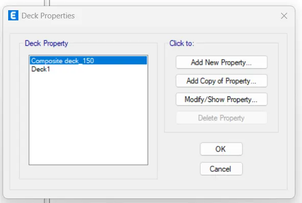
Deck composite slab:
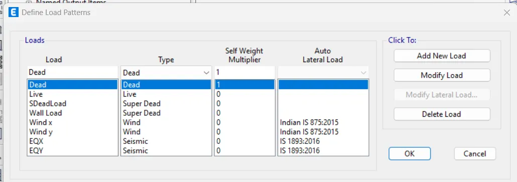
Load pattern, Load combinations & earthquake wind assignments:
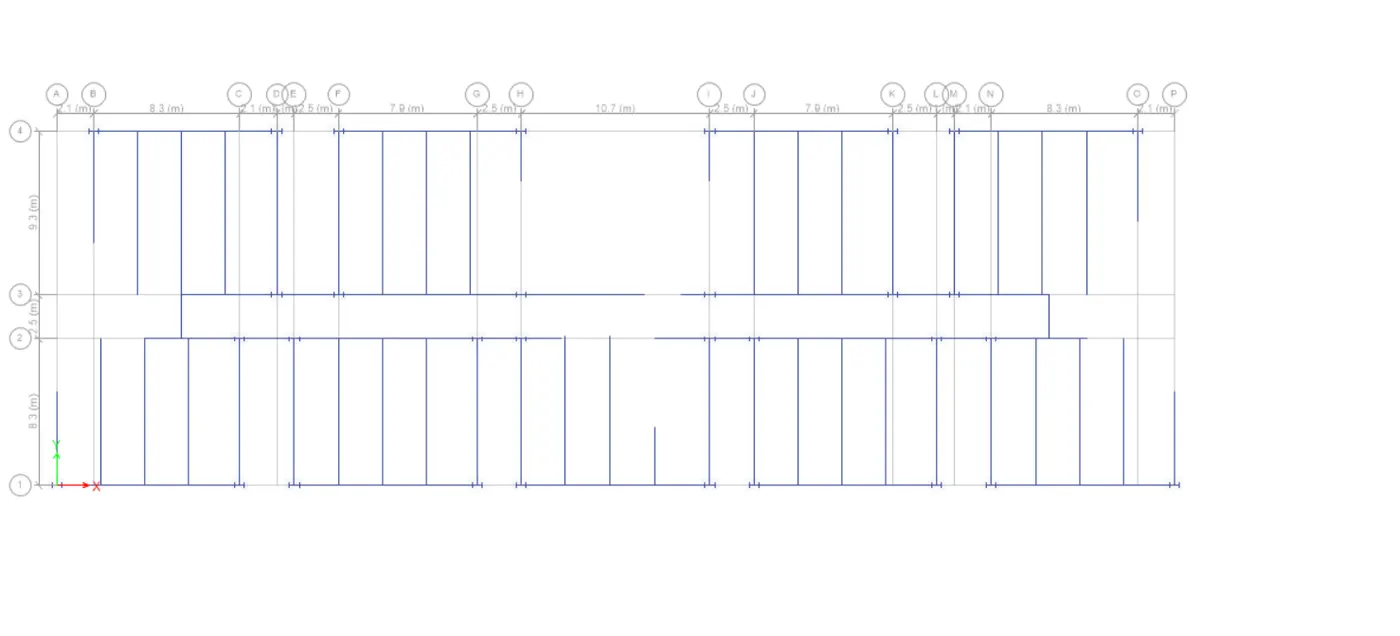
Modelling of columns & steel beams:
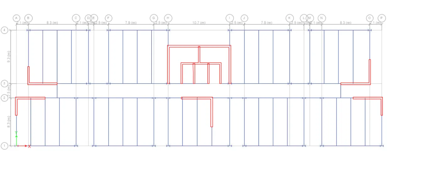
shear walls modelling:
Deck slab assignment:
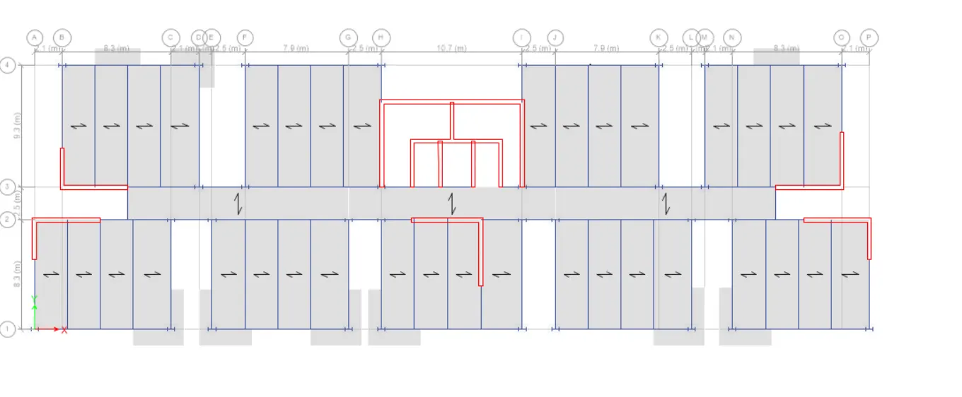
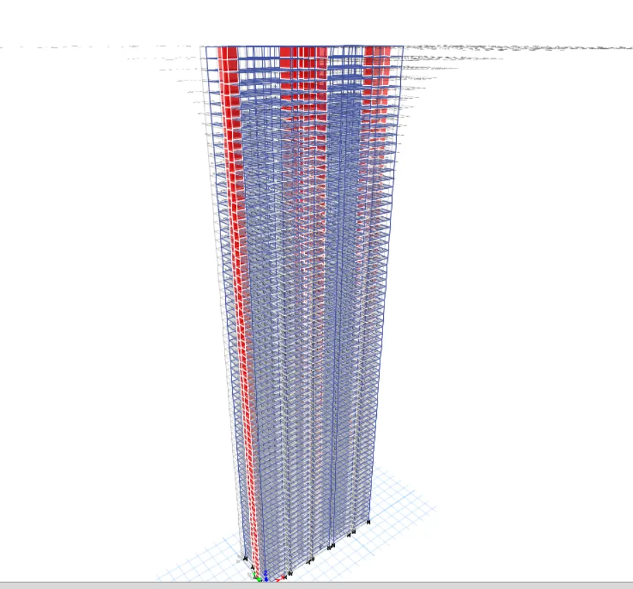
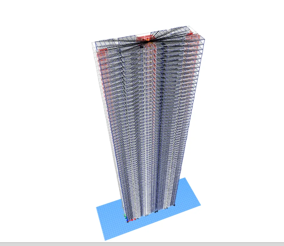
3d view:
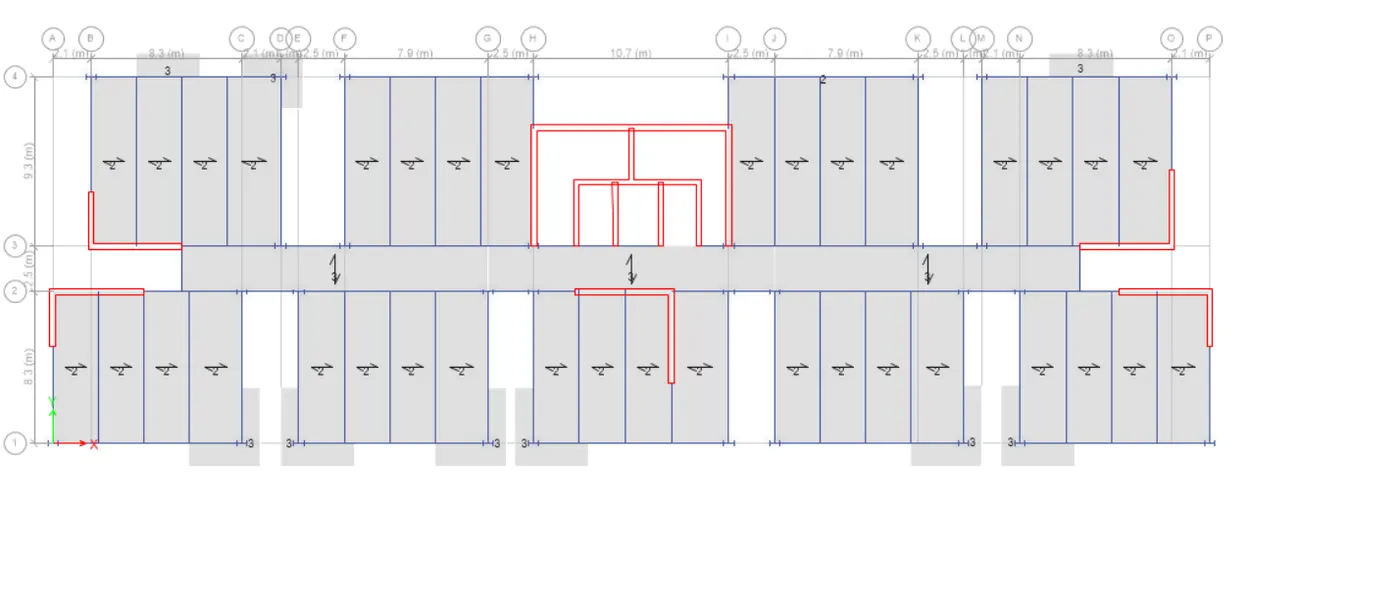
Load assignment:
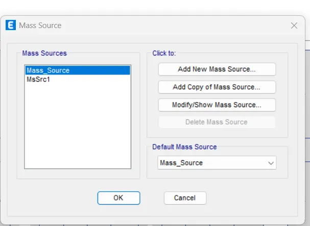
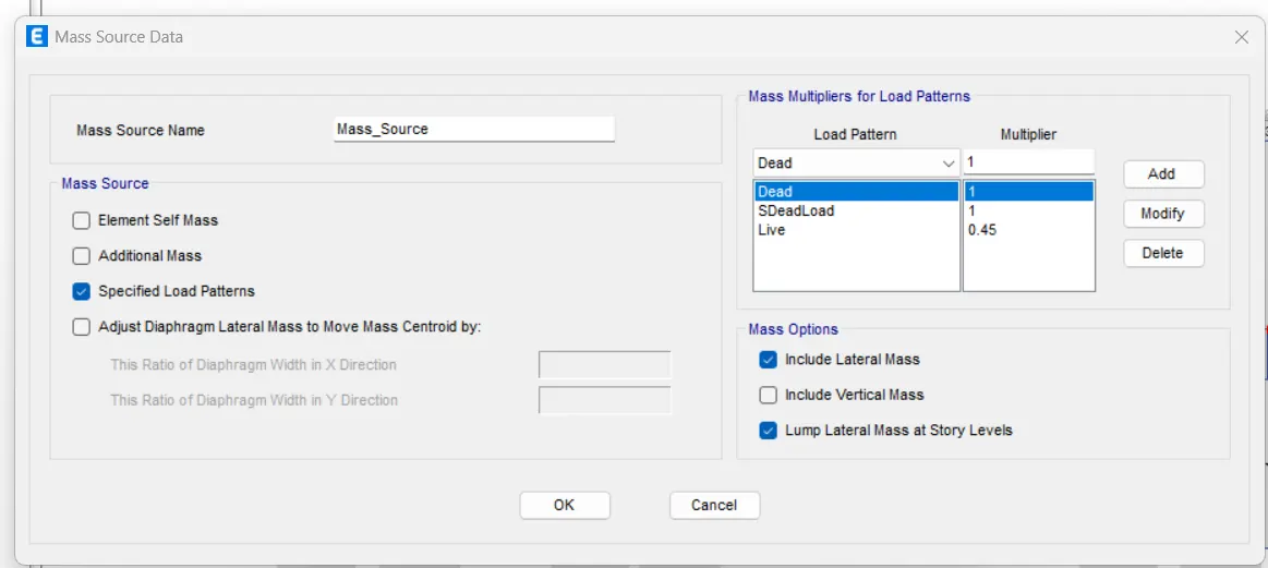
Mass source :
Diaphram:
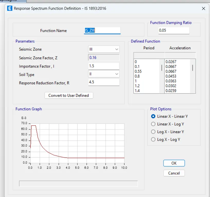
Response Spectrum:
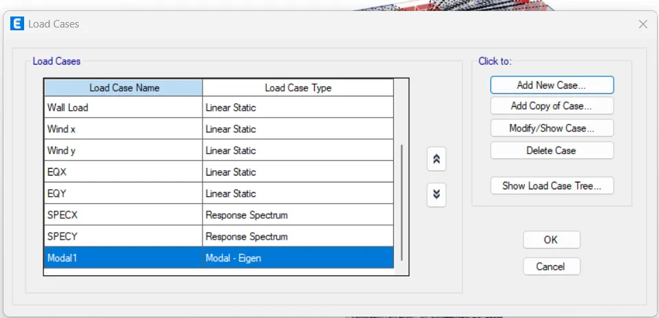
Load Cases:
Composite column design in ETABS:
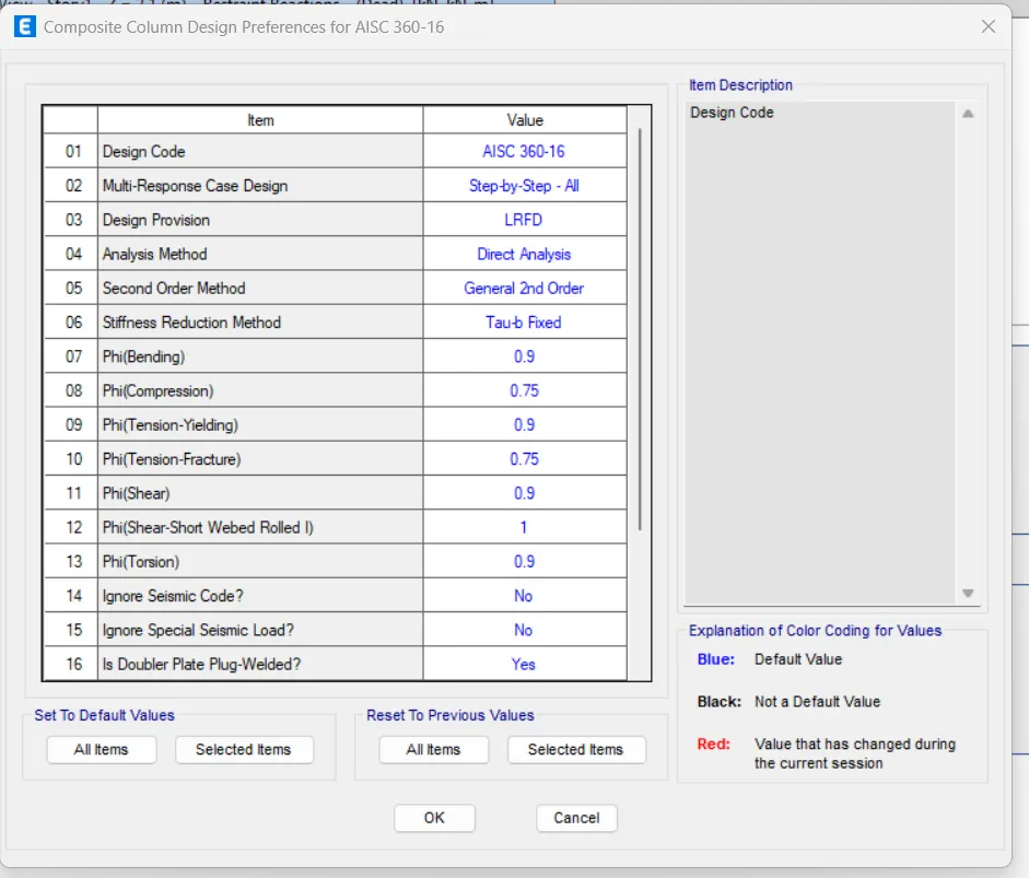
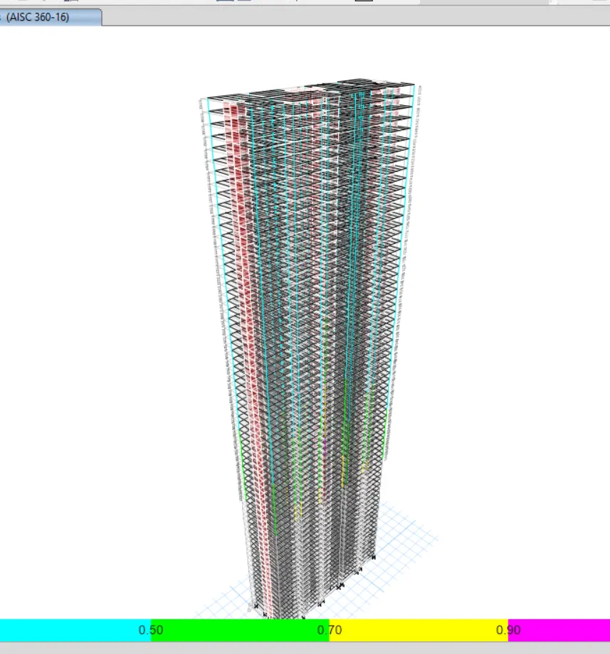
Analysis & composite column design check:
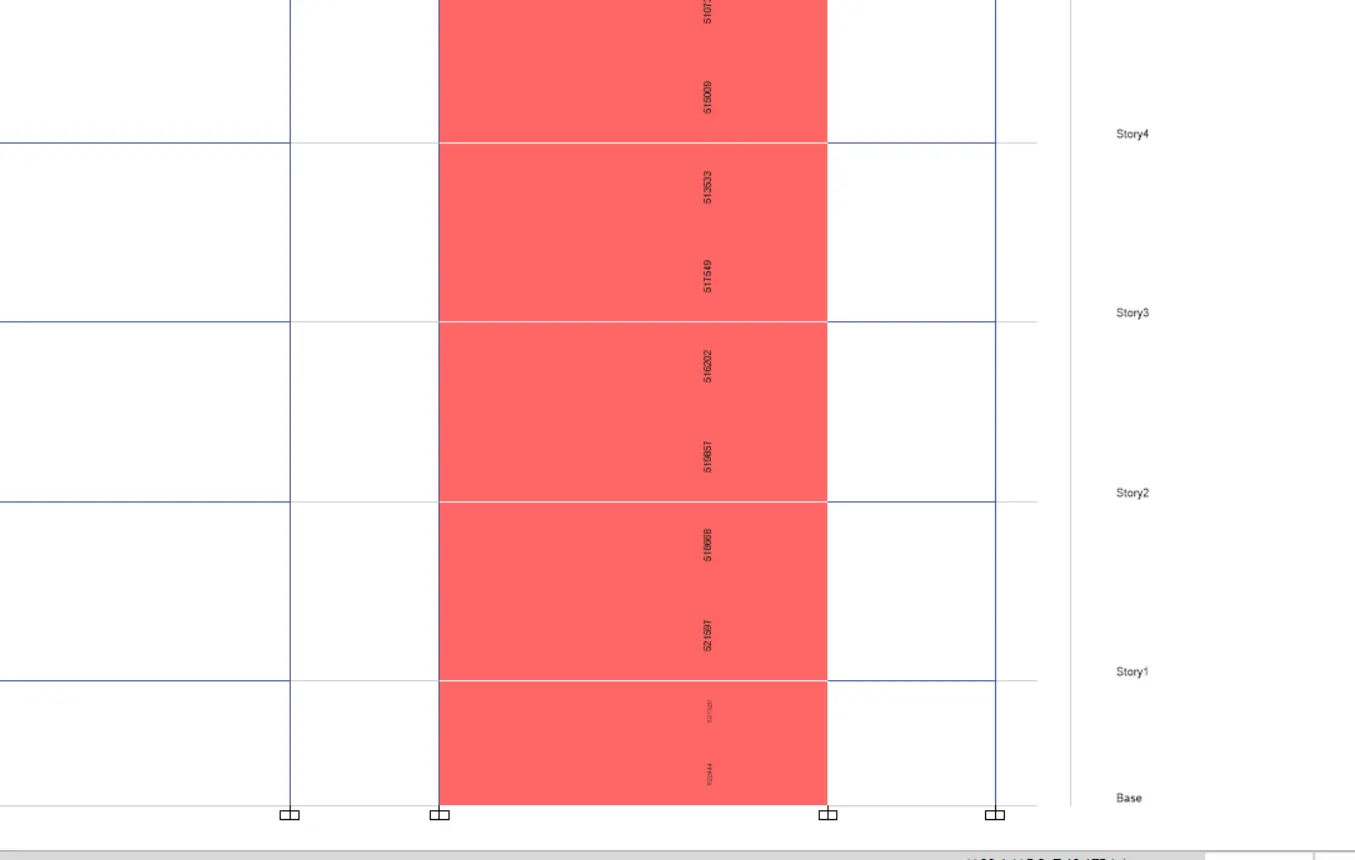
Shear wall Design :
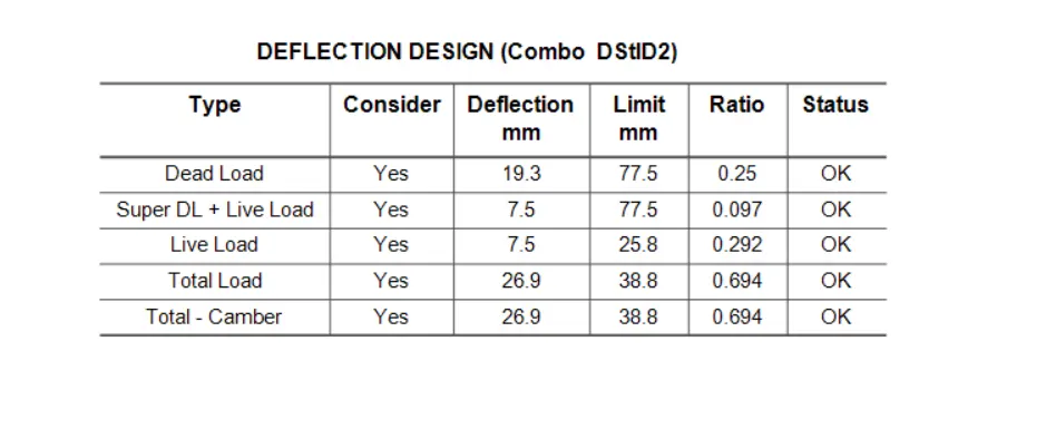
Is understood that, the deflection caused by 100% dead load +10% of imposed load shall be used for determing the frequency of the composite floor. And by verifying the frequency of floor be greater than 3HZ, we can say the foor vibriations are within the tolerant limit.
Deflection of steel beam for vibration load combinnation is noted 0.340 mm
PROCEDURE:
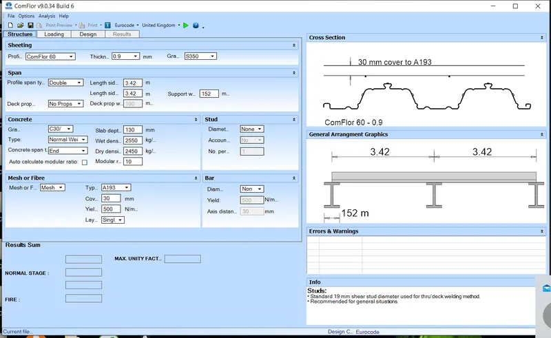
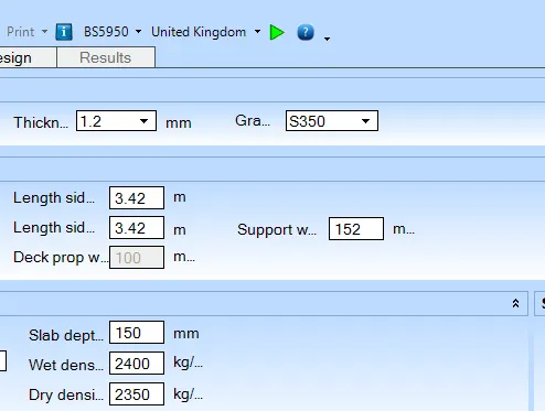
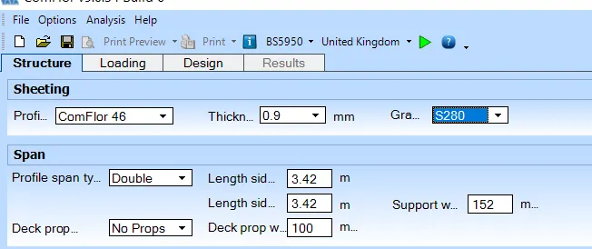
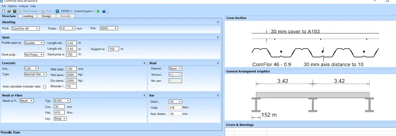
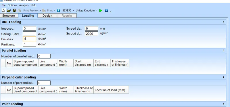
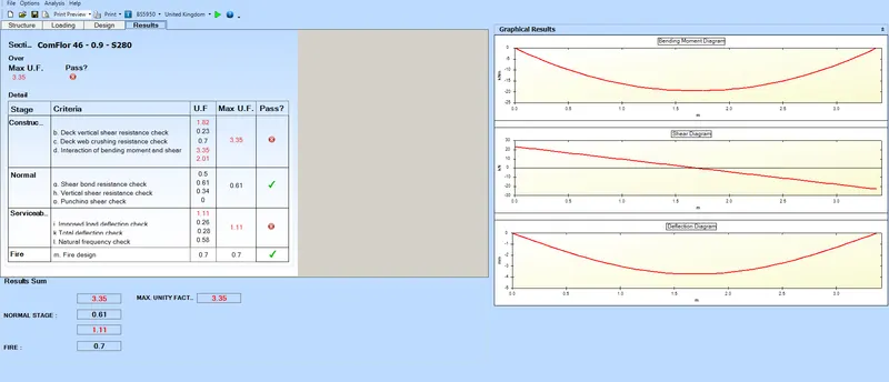
Open comflor software and enter the give data i.e thickness and grade.
then eneter the lengths of given member. enter the lengths of given member enter the span details such as profile span, deck properties and support width then enter the mesh details such as profile span as grade, yield stress. go to the next tab, i,e loading and enter the live and dead load. enter the design methods as fire engineering and enter the fire resistance. in the last step, run the analysis and noote the results.