Project 2 - Modeling of 3 phase Induction Motor Drive
AIM:-
- Model 3 Phase Inverter using Simulink (model the parasitic as well) with a switching frequency of 10Khz using 3 phase Squirrel Cage Induction motor, using V/F method, open loop
Design Parameters:
- Power = 100 HP
- DC Voltage = 800 V
- Output Voltage = 460 VRMS – line to line
- Initial Speed = 1500 RPM
- Final Speed = 1000 RPM
- Initial Load Torque = 10 Nm
- Final Torque=20 Nm
- Torque Step Time = 0.1 secs
For Induction Motor model – use Asynchronous Machine from Simulink with Squirrel Cage Preset Model – 05 , for 100HP Motor
For back emf to speed relation, assume a linear rate from 0.25 to 1, with speed changing from 500 RPM to 2000 RPM
Plot speed, stator voltage (line to line) and frequency.
Plot stator line voltage, phase current
2. Use the 3 phase inductor motor theory to derive the transfer function of 3 phase Induction Motor
3. Model 3 phase induction motor with a 3 phase inverter using Direct Torque control using an Average Model, Implement both torque and flux control to achieve desired power.
Design Parameters:
- Initial Speed = 0 RPM
- Flux Target = 2.5 webers
- DC Voltage = 500 V;
- Fundamental Frequency = 60 Hz
- Speed Step Time = 0.01 secs
- Determine fundamental speed based upon fundamental frequency
- Determine the switching sequence for direct torque control
- Moment of Inertia = 0.1 Kgm^2
- Load Torque Initial = 0 Nm
- Final Load Torque = 50 Nm
- Torque Step Time = 0.03 secs
Motor Parameters: (Create an Average Model)
- Stator Resistance = 0.5 Ohms
- Rotor Resistance = 0.2 Ohms
- Stator Leakage Inductance = 20 mH
- Rotor Leakage Inductance = 10 mH
- Magnetizing Inductance = 200 mH
- Number of Poles = 4
- Torque to Speed
- Model 3 Phase Inverter using Simulink (model the parasitic as well) with a switching frequency of 10Khz using 3 phase Squirrel Cage Induction motor, using V/F method, open loop
Design Parameters:
- Power = 100 HP
- DC Voltage = 800 V
- Output Voltage = 460 VRMS – line to line
- Initial Speed = 1500 RPM
- Final Speed = 1000 RPM
- Initial Load Torque = 10 Nm
- Final Torque=20 Nm
- Torque Step Time = 0.1 secs
For Induction Motor model – use Asynchronous Machine from Simulink with Squirrel Cage Preset Model – 05 , for 100HP Motor
For back emf to speed relation, assume a linear rate from 0.25 to 1, with speed changing from 500 RPM to 2000 RPM
Plot speed, stator voltage (line to line) and frequency.
Plot stator line voltage, phase current
initial speed =1500 rpm
final speed=1000 rpm
torque=10 N-M
For Induction Motor model – use Asynchronous Machine from Simulink with Squirrel Cage Preset Model – 05 , for 100HP Motor
Simulink model:-
Voltage:-
Step:-
V/HZ control:-
Asynchronous machine:-
Ootput waveform:-
V-I STATOR
WHEN CONSTANT TORQUE AT 20 N-M
For back emf to speed relation, assume a linear rate from 0.25 to 1, with speed changing from 500 RPM to 2000 RPM
V/F Control method:
1. Introduction about V/F Control
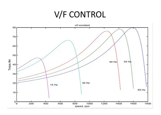
V/F is abbreviated from voltage/frequency. V/F control is an induction motor control method which ensures the output voltage proportional with the frequency, so it maintains a constant motor flux, preventing weak magnetic and magnetic saturation phenomenon from happening.
2. Control Principle
V/F control principle is to produce a circuit called voltage-controller oscillator with oscillator frequency. It is a voltage-dependent capacitance, when subjected to a change in voltage, its capacity will change, and then the change in capacity will cause changes in the oscillation frequency, resulting in variable frequency. This controlled frequency is used to control the frequency of the output voltage, in order to achieve speed changes of the controlled electric motors.
3. Applications of V/F Control
Asynchronous electric motor torque is a result of the interaction of flux and rotor flux. At a rated frequency, if voltage is set to a certain value and only reduce the frequency, then there will be large magnetic flux and magnetic circuit saturation (severely, it will burn motor). Therefore, the frequency and voltage must be changed proportionally. When changing the frequency, we should control the output voltage of AC drive, in order to keep constant flux and avoid weak magnetic and magnetic saturation phenomenon. This control method is commonly applied for fans and pumps.
4. Pros and Cons of V/F Control
Currently, most of the general purpose are using the V/F control method. The VFDs which are of V/F control usually features simple structure. But this kind of VFD adopts open-loop control, so it is difficult to achieve high control performance, moreover, at low frequency, it requires for torque compensation in order to change the low frequency torque characteristics.
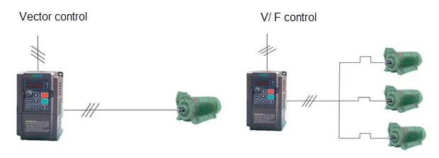
The below image shows the motor control modes supported by Veichi AC70: V/F control and vector motor control mode
Simulink model:
SPWM:
INVERTER:
INDUCTION MOTOR:
Asynchronous Machine is used.
Output:
- This result refers a V/F control drive.
- As frequency increases torque is decresaed.
- Speed is increased from 0 rpm to 1500rpm at 0.3 second.
- 1500rpm remains constant till 1 second.
- Then it drops to 1000rpm and remeins constant till 2 seconds.
2. Use the 3 phase inductor motor theory to derive the transfer function of 3 phase Induction Motor
3. Model 3 phase induction motor with a 3 phase inverter using Direct Torque control using an Average Model, Implement both torque and flux control to achieve desired power.
Design Parameters:
- Initial Speed = 0 RPM
- Flux Target = 2.5 webers
- DC Voltage = 500 V;
- Fundamental Frequency = 60 Hz
- Speed Step Time = 0.01 secs
- Determine fundamental speed based upon fundamental frequency
- Determine the switching sequence for direct torque control
- Moment of Inertia = 0.1 Kgm^2
- Load Torque Initial = 0 Nm
- Final Load Torque = 50 Nm
- Torque Step Time = 0.03 secs
Motor Parameters: (Create an Average Model)
- Stator Resistance = 0.5 Ohms
- Rotor Resistance = 0.2 Ohms
- Stator Leakage Inductance = 20 mH
- Rotor Leakage Inductance = 10 mH
- Magnetizing Inductance = 200 mH
- Number of Poles = 4
- Torque to Speed
DTC motor drive:-
DTC is emerging technique for controlling PWM inverter -fed induction motor IM drives. it allows the precies and quick control of the IM flux and torque without calling of complex control algoritham.
Direct torque control method (DTC):
Another control method, known as direct torque control (DTC), is similar to field oriented control, in that it decouples torque and flux and controls them independently. But DTC controls motor torque directly, without a modulator, so torque response is much faster.
Direct torque control uses two control loops — a speed control loop and a torque control loop — that work together, along with an advanced motor model, to precisely predict stator flux and motor torque
1 – Two motor phase currents and the DC bus voltage are measured. (Motor voltage is determined from the DC bus voltage and the inverter’s switch positions.)
2 – Motor current and voltage are fed to the motor model, which uses advanced mathematical algorithms to produce exact values of the stator flux and motor torque, along with shaft speed, every 25 μs (as fast as 12.5 μs in some drives).
3 – The actual torque and flux values are fed to the torque and flux comparators, which compare them to torque and flux reference values that are provided by the speed control loop (see #6).
The goals of the comparators are to hold the magnitudes of the torque and flux vectors within a narrow hysteresis band around the reference values. This is a primary factor in DTC’s ability to achieve fast torque response without overshoot.
4 – Torque and flux status signals are fed to the optimum pulse selector.
5 – The optimum pulse selector chooses the optimum voltage vector from a lookup table and, based on this, sends pulses to the inverter’s semiconductor switching devices to maintain or change the motor torque as required.
The lookup table provides the optimum voltage vector based on three parameters: whether torque and stator flux each need to be increased or decreased (or, for torque, held constant), and in which sector (60 degree segment) of the space vector plane the stator flux resides.
The semiconductor switching in the inverter again determines motor voltage and current, which determines motor torque and flux, therefore closing the control loop.
6 – The speed control loop contains a speed controller (which consists of a PID controller and an acceleration compensator), a torque reference controller, and a flux reference controller.
The output of the speed controller is fed to the torque reference controller, whose output is the internal reference value for the torque comparator in the torque control loop.
The flux reference controller determines an absolute stator flux value and provides this as the internal reference for the flux comparator in the torque control loop. The flux reference controller is also where flux is controlled and modified to enable inverter functions such as energy optimization and flux braking.
When direct torque control is compared to field oriented control, which also allows tight control of motor speed and torque, two primary differences stand out. First, direct torque control is sensorless — no speed or position encoders are required. It only requires voltage and current measurements. This reduces cost and improves reliability.
The second difference is that direct torque control doesn’t require a modulator (pulse-width modulator, or PWM), so processing time is reduced by a factor of 10, which improves torque response, typically to less than 2 ms. This means torque and speed can be accurately controlled even at low speeds, and full start-up torque is available all the way down to zero speed.
Simulink model:
Induction motor parameters:
Simulink model:-
Command window:-
Three phase ac source:-
Asynchronous motor:-
Braking choper:-
Results:-
1. Vabc,Iabc and Vdc
2. abc,and abc_filter
3.