Project 2 - Modeling of 3 phase Induction Motor Drive
- Model 3 Phase Inverter using Simulink (model the parasitic as well) with a switching frequency of 10Khz using 3 phase Squirrel Cage Induction motor, using V/F method, open loop
Design Parameters:
- Power = 100 HP
- DC Voltage = 800 V
- Output Voltage = 460 VRMS – line to line
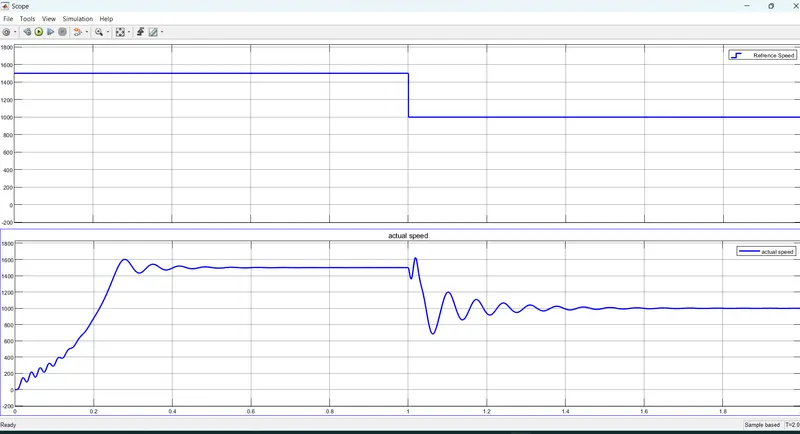
- Initial Speed = 1500 RPM
- Final Speed = 1000 RPM
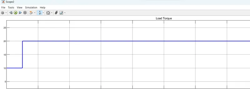
- Initial Load Torque = 10 Nm
- Final Torque=20 Nm
- Torque Step Time = 0.1 secs
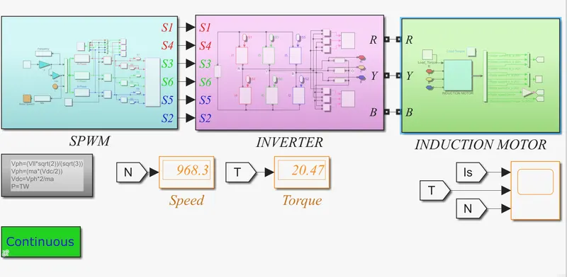
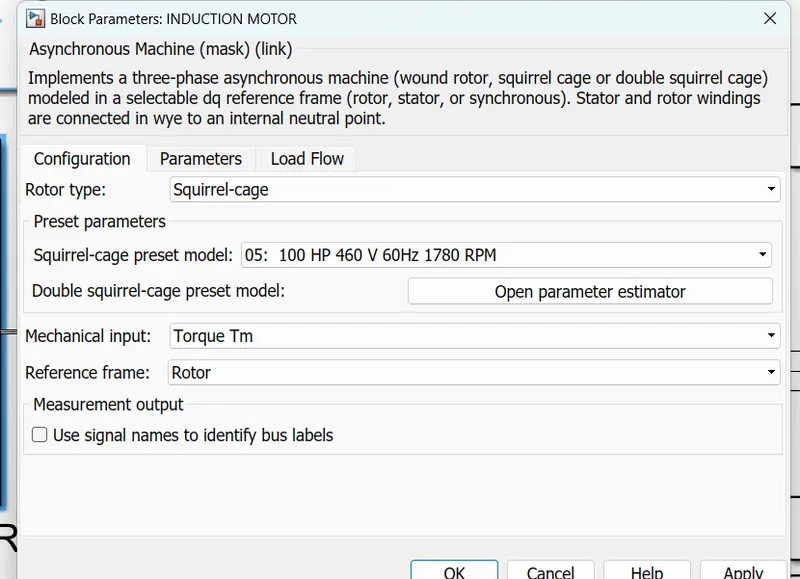
For Induction Motor model – use Asynchronous Machine from Simulink with Squirrel Cage Preset Model – 05 , for 100HP Motor
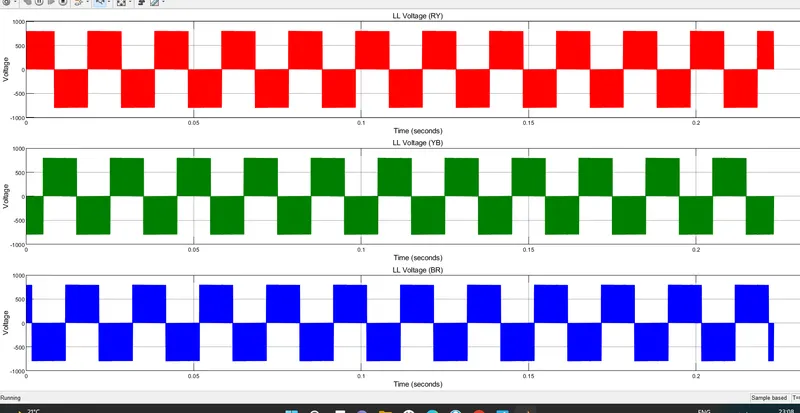
voltage (line to line)
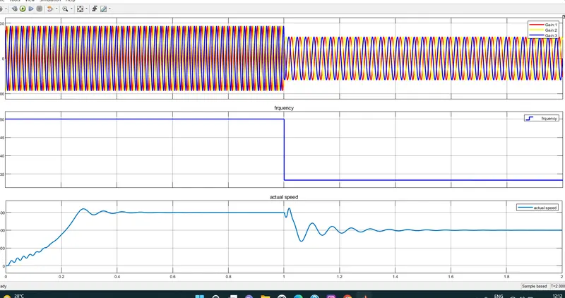
Plot speed, stator voltage (line to line) and frequency.
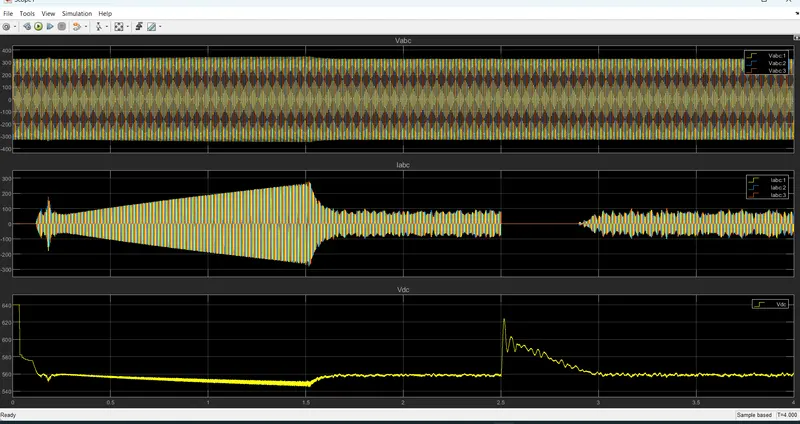
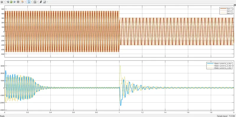
Plot stator line voltage, phase current
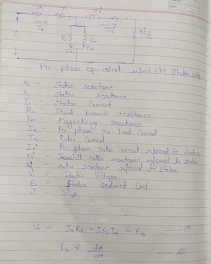
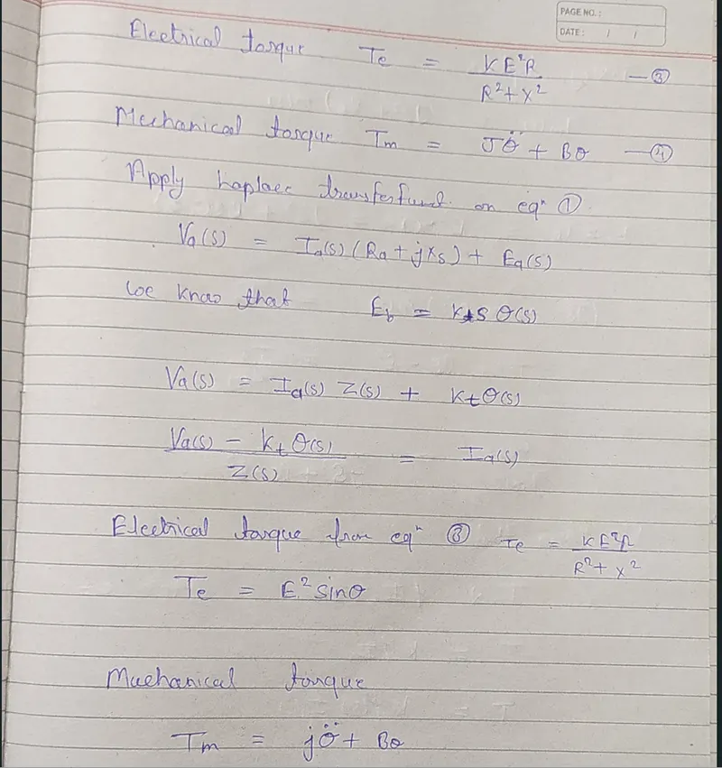
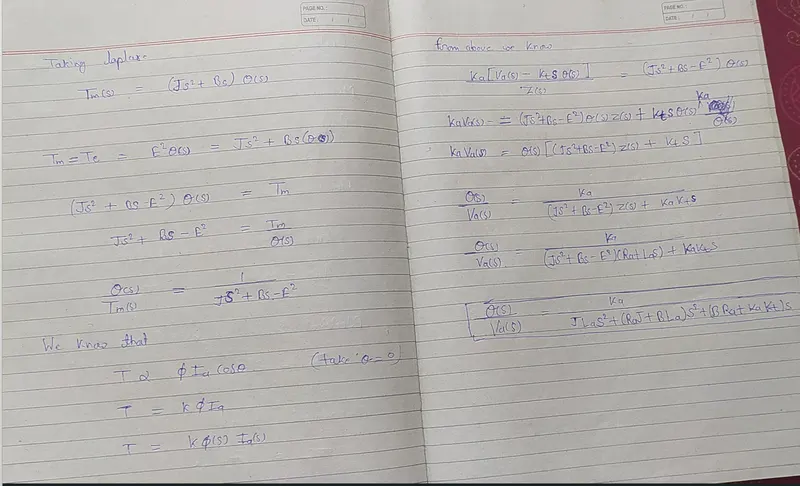
2. Use the 3 phase inductor motor theory to derive the transfer function of 3 phase Induction Motor
3. Model 3 phase induction motor with a 3 phase inverter using Direct Torque control using an Average Model, Implement both torque and flux control to achieve desired power.
Design Parameters:
- Initial Speed = 0 RPM
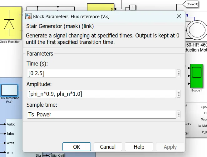
- Flux Target = 2.5 webers
- DC Voltage = 500 V;
- Fundamental Frequency = 60 Hz
- Speed Step Time = 0.01 secs
- Determine fundamental speed based upon fundamental frequency
Ns = 120 f /p
Ns = 120* 60/4
Ns = 1800rpm
- Determine the switching sequence for direct torque control
- Moment of Inertia = 0.1 Kgm^2
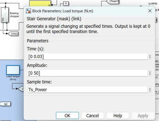
- Load Torque Initial = 0 Nm
- Final Load Torque = 50 Nm
- Torque Step Time = 0.03 secs
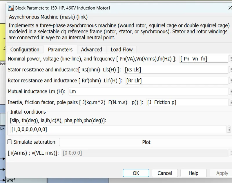
Motor Parameters: (Create an Average Model)
- Stator Resistance = 0.5 Ohms
- Rotor Resistance = 0.2 Ohms
- Stator Leakage Inductance = 20 mH
- Rotor Leakage Inductance = 10 mH
- Magnetizing Inductance = 200 mH
- Number of Poles = 4
- Torque to Speed
DTC is an emerging technique for controlling PWM inverter-fed induction motor IM drives. it allows the precise and quick control of the IM flux and torque without calling on a complex control algorithm.
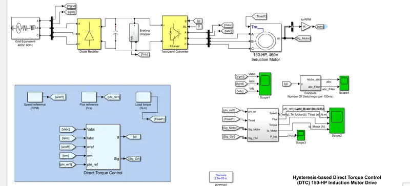
Load torque
flux ref
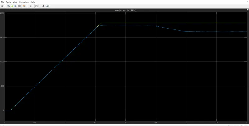
Speed ref
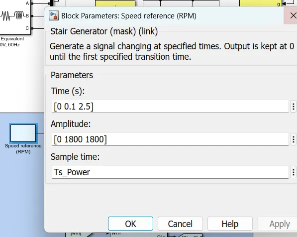
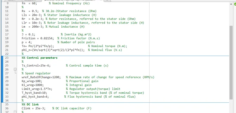
Simulation results
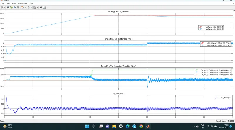
refrence speed vs actual speed
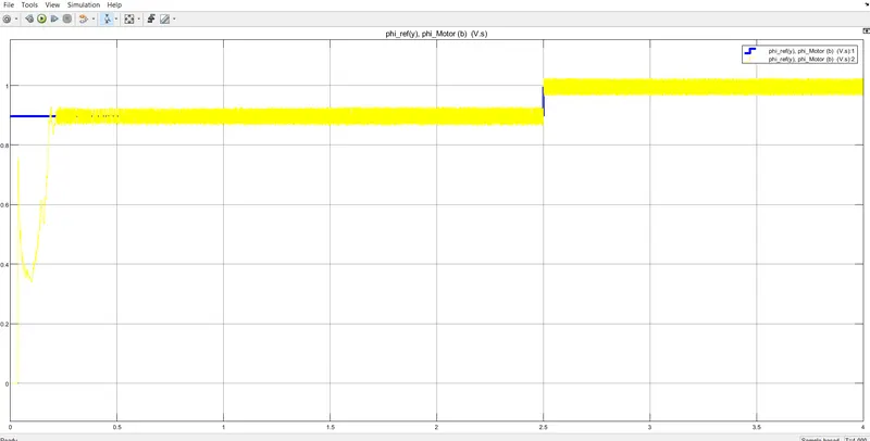
Phi refrence vs actual phi
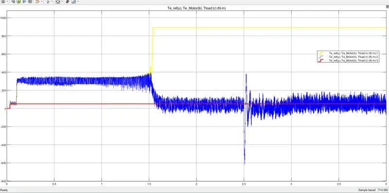
Torque ref /moror torque/
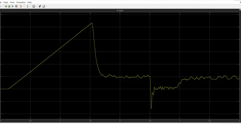
power