Project 2 - Modeling of 3 phase Induction Motor Drive
AIM:
1. Model 3-Phase Inverter using Simulink (model the parasitic as well) with a switching frequency of 10Khz using 3-phase Squirrel Cage Induction motor, using V/F method, open loop,
Design Parameters:
- Power = 100 HP
- DC Voltage = 800 V
- Output Voltage = 460 VRMS – line to line
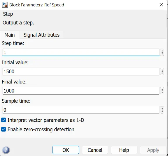
- Initial Speed = 1500 RPM
- Final Speed = 1000 RPM
- Initial Load Torque = 10 Nm
- Final Torque=20 Nm
- Torque Step Time = 0.1 secs
For Induction Motor model – use Asynchronous Machine from Simulink with Squirrel Cage Preset Model – 05 , for 100HP Motor
For back emf to speed relation, assume a linear rate from 0.25 to 1, with speed changing from 500 RPM to 2000 RPM
Plot speed, stator voltage (line to line) and frequency.
Plot stator line voltage, phase current.
Solution:
V/F control:
- V/F control, also known as voltage/frequency control, is a method of controlling the speed of an induction motor by varying the ratio of voltage to frequency supplied to the motor.
- The basic idea behind V/F control is to maintain a constant magnetic flux in the motor as the speed changes.
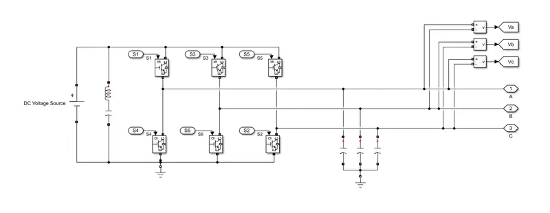
- The V/F control technique involves the use of a PWM (Pulse Width Modulation) inverter to generate variable voltage and frequency waveforms. The inverter converts the DC voltage into AC voltage with a variable frequency and voltage. By controlling the frequency and voltage of the AC power supplied to the motor, the V/F ratio can be maintained and the motor speed can be controlled.
- In V/F control technique, the voltage and frequency are kept proportional to each other to maintain the constant V/F ratio. As the frequency is increased, the voltage supplied to the motor is also increased to maintain the V/F ratio. Similarly, as the frequency is decreased, the voltage is also decreased. This maintains a constant magnetic flux in the motor, allowing it to operate at a constant torque and efficiency.
Simulink model of 3-phase Induction Motor Drive using V/F control:
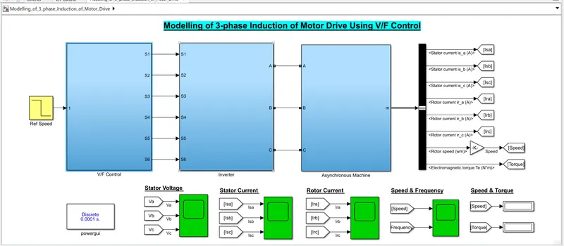
V/F Control model:
- Whenever three phase supply is given to three phases induction motor rotating magnetic field is produced which rotates at a synchronous speed given by

- In three phase induction motor emf is induced by induction similar to that of a transformer which is given by

Where, K is the winding constant,
T is the number of turns per phase, and f is frequency.
- Now, when we change frequency synchronous speed changes, but if we decrease in frequency, flux will increase and this change in the value of flux causes saturation of rotor and stator cores which will further cause an increase in the no-load current of the motor.
- So, it is important to maintain flux φ as constant and it is only possible if we change voltage. i.e if we decrease frequency flux increases but at the same time if we decrease voltage flux will also decrease causing no change in flux and hence it remains constant.
- Here we are keeping the ratio of V/f constant. Hence its name is the V/ f method. For controlling the speed of three phase induction motor by the V/f method, we have to supply a variable voltage and frequency which is easily obtained by using a converter and inverter set.
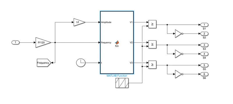
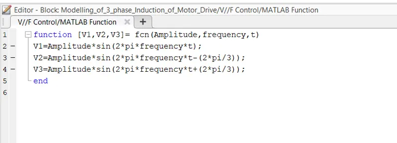
MATLAB Function block:
- MATLAB function block is a Simulink block that allows users to include MATLAB code within a Simulink model. This block provides a way to write custom functions in MATLAB code and use them as blocks within a Simulink model.
- The MATLAB function block can be found in the Simulink Library Browser under the User-Defined Functions category. Once added to a Simulink model, the block provides an editable text box where users can write MATLAB code that will be executed during simulation.
- Users can define inputs and outputs for the MATLAB function block, and use the input and output signals in their MATLAB code.
- So, by using Matlab Function Block, we have defined functions for the PWM switching of three phase inverter.
Three Phase Inverter:
Reference Speed:
With the help of Step block in simulink, we have given intial speed as 1500rpm and then it decreases to 1000rpm with step time of 1 sec.
Reference Torque:
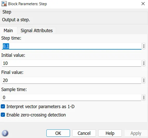
Torque references using a step block:-
- Initial Load Torque = 10 Nm
- Final Torque=20 Nm
- Torque Step Time = 0.1 secs
Asynchronous Machine:
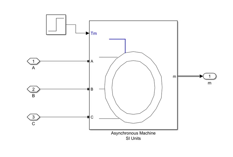
The output of inverter is given to the induction motor which has ratings of 100HP, 460V,1780rpm.
Output:
Speed & Torque:
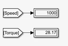
- The rotor speed and torque are shown with help of display block as shown below.
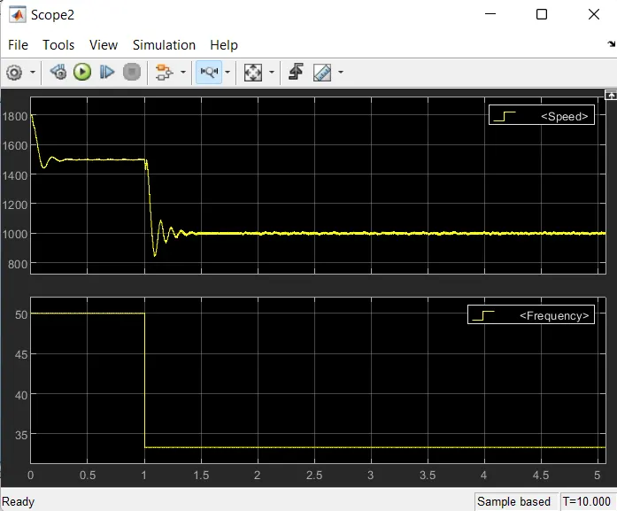
- As by using step block, we have given initial speed of 1500rpm as per the requirement with step time of 1 sec and finally we get the output speed reduced to the 1000rpm.
- Also, we have given intial torque of 10Nm with step time of 0.1 sec and then it was increased upto 20Nm. In display block we have seen that the final torque reached to the value of 28.17Nm.
Speed & Frequency:
- From the plot we have observed that intially the speed of motor is constant at 1500rpm upto 1sec and then it reduces to 1000rpm as per the given requirement using V/F control.
- Simillarly, the initial frequency of 50Hz at 1500rpm changes with respect to the speed which is decreases upto the 33.33Hz as shown in below.
Stator Current:
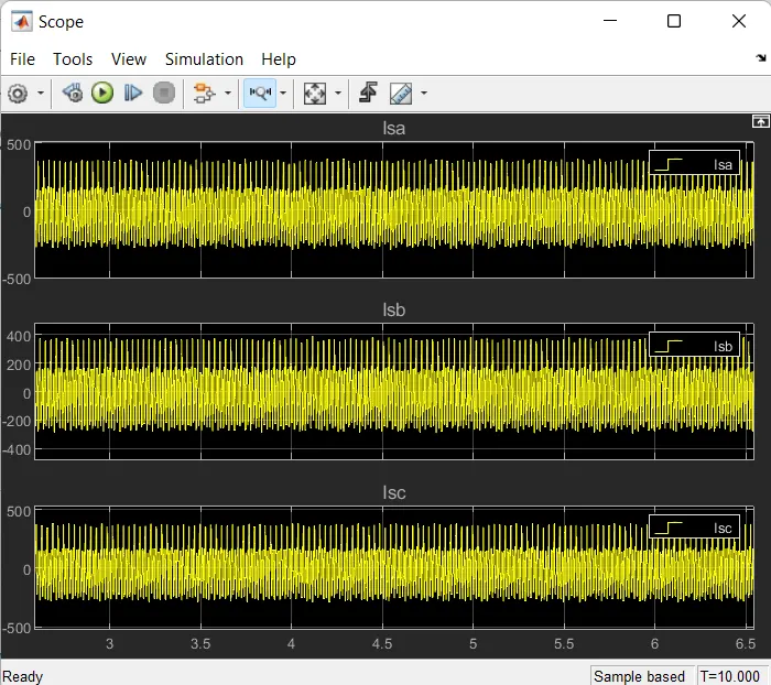
- The stator current of induction motor is shown in below,
Stator Voltage:
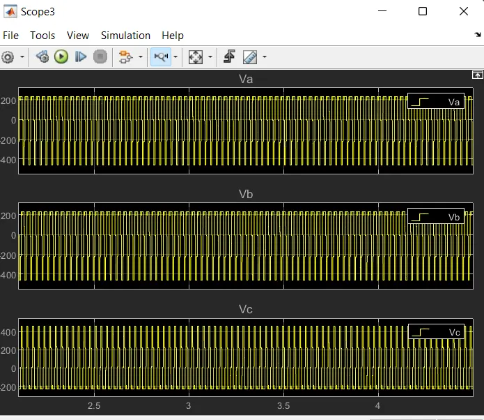
- The line to line stator voltage of induction motor is shown in below,
Rotor Current:
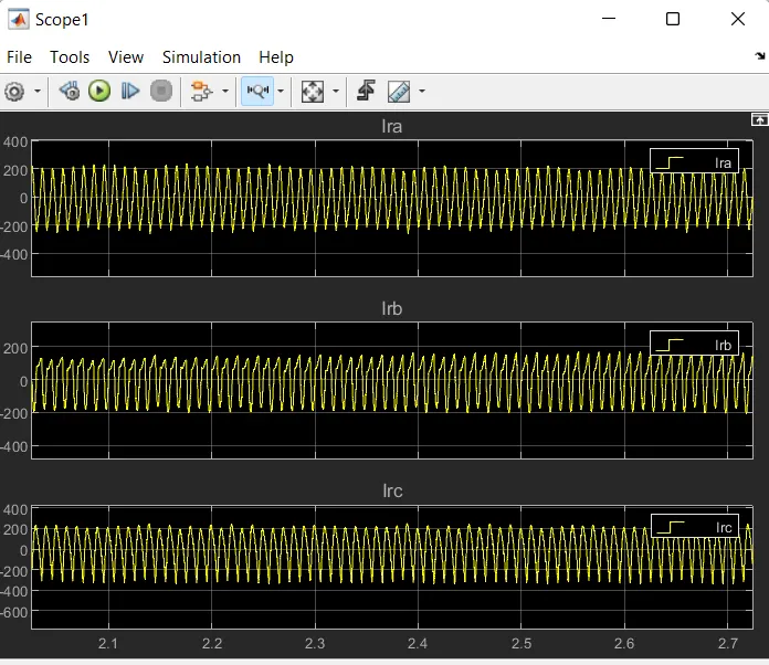
- The rotor current of induction motor is shown in below,
Conclusion:
- As we know that the speed of the induction motor depends on the V/f ratio. It is also possible to control the speed only by changing the frequency alone, if this is done so, air gap flux will saturate at some frequency. The saturation of air gap flux has to be avoided because it causes a lot of harmonics.
- So, by keeping V/F ratio i.e flus as constant we have achieved the requirements like speed and torque variation of induction motor.
- Although most of the control and design part is at the inverter section using an inverter for speed control of the induction motor will be smooth, and flexible and also there will be remarkable limiting of transients when we change the V/f ratio from one value to another value.
- The DC link capacitor, parasitic inductance as well as snubber circuit and filter circuit is used for smoothing the switching operation of power switches and we get the stability in the speed control of induction motor.
- So, controlling of induction motor is achieved using V/F control technique.
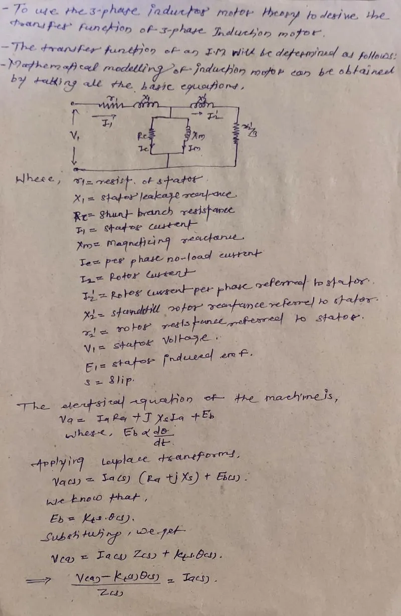
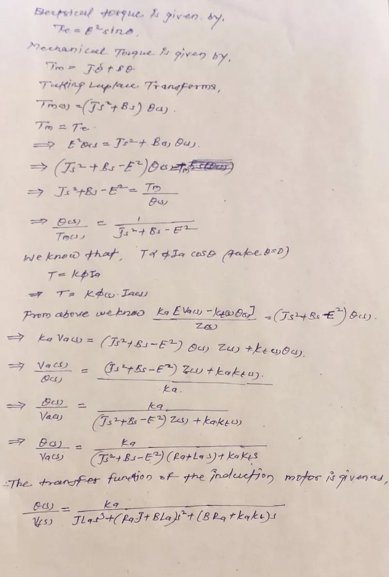
2. Use the 3-phase inductor motor theory to derive the transfer function of 3 phase Induction Motor
Solution:
Derivation of the transfer function of 3 phase Induction Motor:
3. Model 3-phase induction motor with a 3 phase inverter using Direct Torque control using an Average Model, Implement both torque and flux control to achieve desired power.
Design Parameters:
- Initial Speed = 0 RPM
- Flux Target = 2.5 webers
- DC Voltage = 500 V;
- Fundamental Frequency = 60 Hz
- Speed Step Time = 0.01 secs
- Determine fundamental speed based upon fundamental frequency
- Determine the switching sequence for direct torque control
- Moment of Inertia = 0.1 Kgm^2
- Load Torque Initial = 0 Nm
- Final Load Torque = 50 Nm
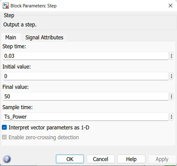
- Torque Step Time = 0.03 secs
Motor Parameters: (Create an Average Model)
- Stator Resistance = 0.5 Ohms
- Rotor Resistance = 0.2 Ohms
- Stator Leakage Inductance = 20 mH
- Rotor Leakage Inductance = 10 mH
- Magnetizing Inductance = 200 mH
- Number of Poles = 4
- Torque to Speed
Solution:
Direct Torque Control (DTC):
To acquire high enactment, Direct Torque Control (DTC) is a technique used in AC drive systems. In this paper, based on the hysteresis controller, a very simple improved DTC scheme is proposed for induction motor drive. Owing to its simple assembly & effective enactment, DTC is used for AC as well as DC drive as compared to other controlling schemes. the paper approaches mitigation of the ripples in torque by varying the predictable 3-level torque-hysteresis controller used in DTC. The expansion of distinctive switching approach has been generated for chosen voltage-vector. Based on ripple content simulation results carried out in MATLAB/SIMULINK for torque-hysteresis controller to minimize the ripples.
Electrical Model:
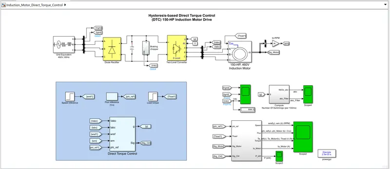
The electrical energy is supplied by a three-phase AC/DC diode rectifier connected to a 460 V, 60 Hz grid equivalent. The DC bus is connected to a three-phase, two-level converter. This converter generates the variable voltage and frequency required for variable-speed operation of the 150 HP induction motor. In addition, a braking chopper is connected to the DC bus in order to dissipate the kinetic energy of the motor during deceleration.
An inverter-fed induction motor drive can be controlled through various techniques depending on application, desired performance, and controller design complexity. Commonly used schemes are scalar control (V/Hz control or open loop flux control) or vector control (field-oriented control or direct torque control). This example uses a hysteresis-based direct torque control (DTC) technique.
Direct Torque Controller:
Direct torque control (DTC) is a technique that allows you to instantaneously control the motor magnetic flux and its electromagnetic torque in a decoupled way. Controlling the torque directly permits accurate static and dynamic speed regulation. The main components of the DTC subsystem are:
-
Flux and Torque Calculation — The stator flux linkage is estimated by integrating the stator voltages, and torque is calculated based on the estimated flux and the motor currents.
-
Speed Regulator — The regulator compares the actual motor speed with the speed reference and generates the torque reference.
-
Hysteresis Control — The calculated flux magnitude and torque are compared with the reference values. When the resulting flux or torque error crosses either the positive or negative hysteresis band value, a control signal is activated in order to correct the error.
-
Optimal Switching — Pulses to the motor inverter are produced based on the control signals generated by the hysteresis control and the stator flux linkage position.
The figure below illustrates the strategy used to determine the best voltage vector when the flux linkage is located in sector 0.
The image shows four cases:
-
V3 is selected when the electromagnetic torque should be increased and the flux should stay unchanged. Selecting the V3 voltage vector speeds up the flux and thus applies an acceleration torque to the rotor while slightly decreasing the flux magnitude.
-
V2 is selected when the electromagnetic torque should be increased and the flux should be increased. Selecting the V2 voltage vector slightly speeds up the flux and increases its magnitude.
-
V6 is selected when the electromagnetic torque should be reduced and the flux should be increased. Selecting the V6 voltage vector slows down the flux and thus applies a deceleration torque to the rotor while increasing the flux magnitude.
-
V5 is selected when the electromagnetic torque should be reduced and the flux should stay unchanged. Selecting V5 the voltage vector applies a deceleration torque to the rotor and slightly decreases the flux magnitude. Note that voltage vectors V1 and V4 are not selected in sector 0. Using these two vectors would have too much negative impact on the desired flux value. Finally, to keep the torque and the flux unchanged, the null voltage vectors V0 or V7 are selected.
When the flux linkage vector moves to sector 1, the selected voltage vectors become V4 for case 1, V3 for case 2, V1 for case 3, and V6 for case 4, and vectors V2 and V5 are not used. This 60 degree shift in the voltage vectors happens each time the flux linkage vector enters a new sector.
Simulation:
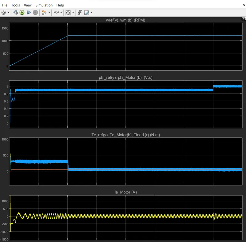
- Run the simulation and observe the waveforms on Scope2. Initially, the flux reference is set to 0.9 V.s.
- At 0.1 s, the speed reference is set to 1500 RPM and the motor starts to accelerate. The motor speed precisely follows the speed reference, whose maximum rate of change is limited to 1200 rpm/s. The 1500 RPM set point is reached at 1.35 s.
- At 1.5 s, a load torque of 500 N.m is applied to the motor. The DTC control operates to maintain the motor speed at 1500 RPM.
- At 2 s, the load torque is reduced to 50 N.m and at 2.5 s, the speed reference is reduced to 500 RPM. Observe on Scope 1 that the braking chopper operation dissipates the kinetic energy produced by the motor in order to avoid overvoltage on the DC bus. Finally, at 3.5 s, the flux reference is increased from 0.9 to 1.0 V.s.
Torque Reference:
- Load Torque Initial = 0 Nm
- Final Load Torque = 50 Nm
- Torque Step Time = 0.03 secs
Output Plots:
- Below graph shows the Speed, Flux, torque and Current of the Induction motor.
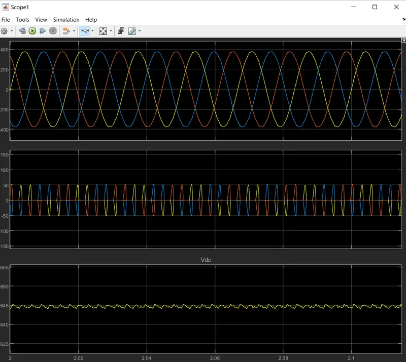
Input Voltage and Current Parameters:
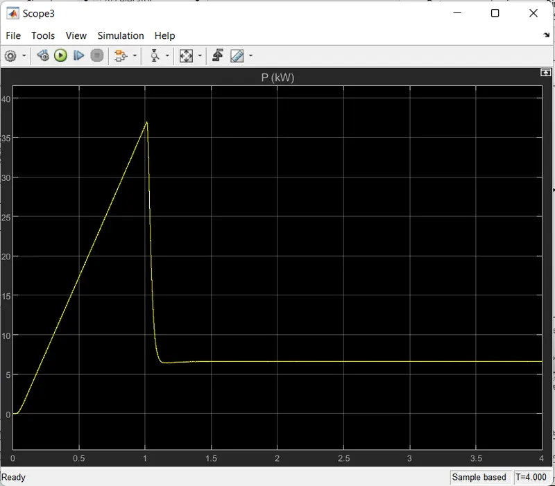
Output Power:
CONCLUSION:
- For any IM drives, direct torque control is one of the best controllers proposed so far. It allows decoupled
control of motor stator flux and electromagnetic torque. From the analysis it is proved that, this strategy of
IM control is simpler to implement than other vector control methods as it does not require pulse width
modulator and co-ordinate transformations. - The estimation accuracy of stator flux is very much essential which mostly depends on stator resistance
because an error in stator flux estimation will affect the behavior of both torque and flux control loops. The
torque and current ripple can be minimized by employing space vector modulation technique. A new strategy is introduced further to get quick response by introducing one “modified flux error block” and proved by MATLAB/SIMULINK model.