Project 2 - Modeling of 3 phase Induction Motor Drive
AIM: The aim is to design the 3 Phase Inverter using Simulink with switching frequency of 10KHz and Controlling the 3 phase Squirrel Cage Induction motor, using V/F method from 3 Phase Inverter.
Given Parameters:
- Power = 100 HP
- DC Voltage = 800 V
- Output Voltage = 460 VRMS – line to line
- Initial Speed = 1500 RPM
- Final Speed = 1000 RPM
- Initial Load Torque = 10 Nm
- Final Torque=20 Nm
- Torque Step Time = 0.1 secs
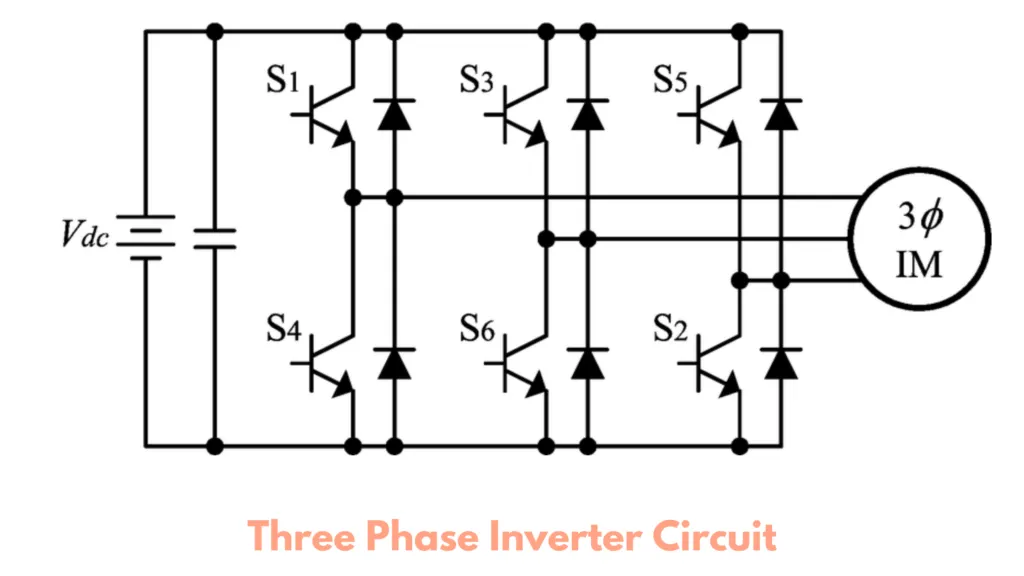
The main function of this kind of inverter is to change the input of DC to the output of three-phase AC. A basic 3 phase inverter includes 3 single phase inverter switches where each switch can be connected to one of the 3 load terminals.
Generally, the three arms of this inverter will be delayed with 120 degrees angle to generate a 3 phase AC supply.
The switches used in the inverter have 50% of ratio and switching can be occurred after every 60 degrees angle. The switches like S1, S2, S3, S4, S5, and S6 will complement each other. In this, three inverters with single-phase are placed across a similar DC source. The pole voltages within the three-phase inverter are equivalent to the pole voltages within the half-bridge inverter with a single phase.
V/F Control :
V/f control is a method to control a ratio between primary voltage (V) to be applied to the induction motor and
inverter output frequency (f) to be constant. This control enables to obtain satisfactory torque characteristics in a wide
frequency range by maintaining the magnitude of the rotating magnetic field vector independently from the inverter
output frequency when voltage drop due to a primary winding resistance is ignored.
However, as the frequency declines, the voltage drop due to the primary winding resistance becoming too large to be
ignored, and consequently, it becomes impossible to obtain sufficient torque. In such a case, applying a higher voltage
than the voltage calculated from the V/f ratio which was used for a high frequency makes it possible to secure enough
torque even at a low frequency.
Whenever three phase supply is given to three phases induction motor rotating magnetic field is produced which rotates at a synchronous speed given by
SIMULINK MODEL:
The Simulink model of 3phase Inverter by using V/F method for controlling a 3 phase Squirrel Cage Induction Motor consists of following blocks:
- DC Voltage source
- IGBT
- Asynchronous Machine(SI Units)
- Saturation
- Step
- Terminator
- Product
- Bus selector
- DMux
- From
- Goto
- Voltage Measurement
- Relational Opeartor
- Repeating Sequence
- Gain
- Power Gui
- Constant
- Scope
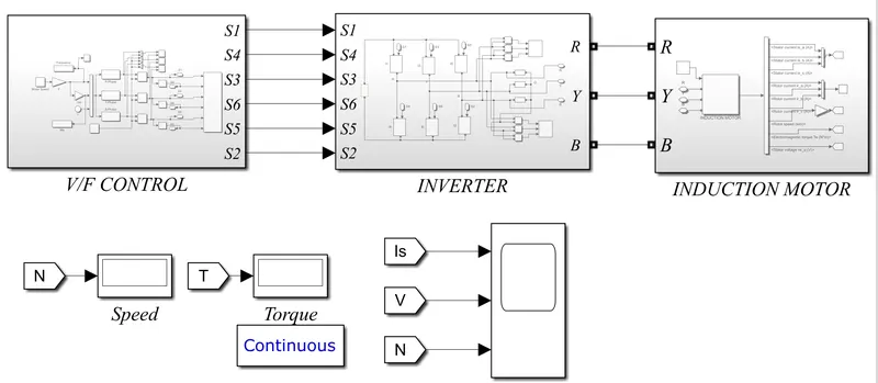
The above model consists of 3 Subsystems of V/F Controller, Inverter and Induction Motor.
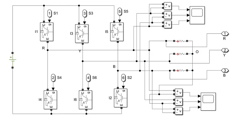
The 3Phase Inverter Model is supplied with DC voltage of 800V. The inverter has 3legs with each leg having 2 number of Power Switching device IGBT. These 6 Power switches will operate for both high(positive signal) and low(negative) Signal operation. The Gate Signals for Switches is generated by using V/F Control Method. A voltage measurment block is used to measure the Line to Line voltage and Line to Neutral Voltage.
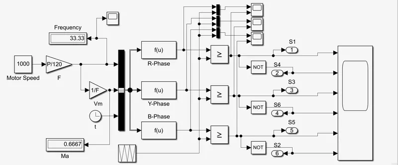
For V/F Control Method the Motor Speed in RPM is given as reference speed. These Reference speed when multiplied by P/120 gives the frequency. The frequency, Vm and Clock signal are given as input to bus creator and bus creator operator is given to Function block where sine wave equation is entered to generate 3 sinewaves each lagging with phase displacement of 120degree toeach other. A repeating Sequence blockmis used to generate triangular wave. These Triangular wave is compared with 3 sine waves by using relational operator. When Sinewave output isn greater than Triangular wave then the high gate pulse is generated. A NOT gate is used to generate the opposite gate pulse. These gate pulses are then given to three phase inverter IGBTs. The gate pulses generated from NOT gate is connected to bottom phase of inverter.
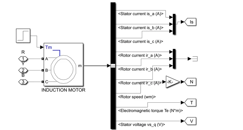
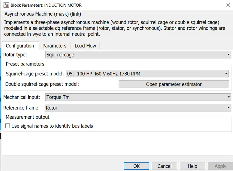
For Induction Motor Asynchronous Machine block is used with parameters 100HP 460V 1730RPM Squirrel Cage rotor Motor. A step input is applied as load torque. At initial 10NM of torque is applied then the torque is increased to 20Nm. The output of three phase Inverter is connected to Motor. The block gives output of Stator Current, Stator Voltage, Motor Torque and Motor RPM.
RESULTS:
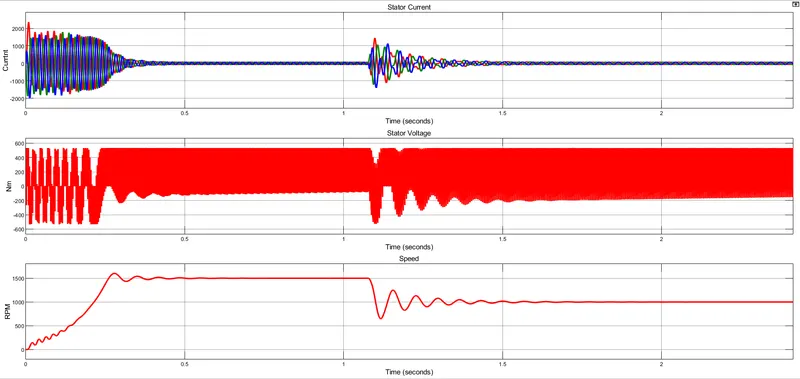
- The 1st graph shows the stator current of 3phases of stator windings.
- The 2nd graph shows the output of Stator Voltage.
- The 3rd graph shows the Motor Speed in RPM. WHen the motor is starting it draws hight amunt of staring current, the RPM settles at 1500RPM after some oscillations in about 0.4seconds. After 1.1 seconds the speed is reduced to 1000RPM.
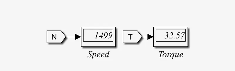
At 1500RPM the motor generates a torque of 32.57Nm.

The above image shows the 3Phase Stator Current waveforms.

The above image shows the Stator Voltage waveform.
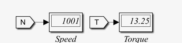
At 1000RPM the motor generates a torque of 13.25NM.
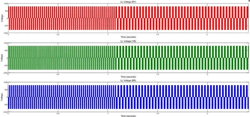
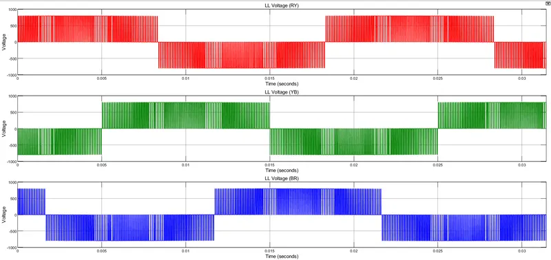
- The above images shows the Line to Line voltage of the 3Phase Inverter each with 120degree of phase displacement. The Voltage oscillated between +550V to -550V.
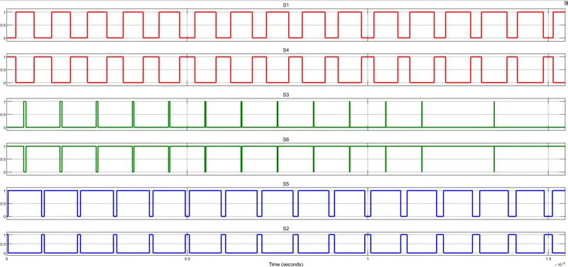
The above image shows the 6 gate pulses generated for Inverter.
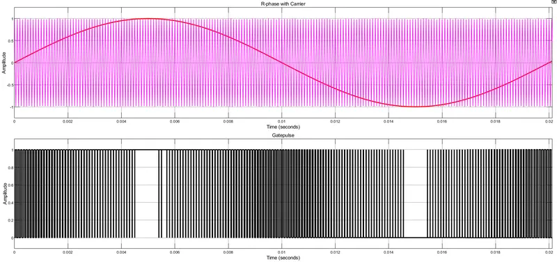
The above image shows the gate pulse generated for Rphase wrt Carrier wave. The gate pulse is high when sinewave is higher than triangular wave.
CONCLUSION: The Speed of 3Phase Induction Motor is controlled by using 3Phase Inverter by applying V/F Method, model and its results are explained.
2. Use the 3 phase inductor motor theory to derive the transfer function of 3 phase Induction Motor.
A 3-phase induction motor consists of a stator and a rotor. The stator carries a 3-phase stator winding while the rotor carries a short-circuited winding called rotor winding. The stator winding is supplied from a 3-phase supply. The rotor winding drives its voltage and power from the stator winding through electromagnetic induction and hence the name.
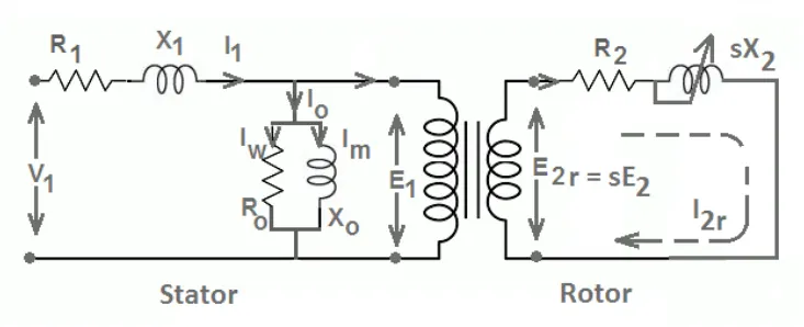
Equivalent Circuit of Induction Motor
`R_1`= Stator Resistance
`X_1`= Stator Leakage Reactance
`I_1`= Stator Current
V = Stator Voltage
`R_0`= Shunt Resistance
`X_0`= Magnetizing Reactance
`E_1`= Stator Induced emf
`R_2` = Rotor Resistance
`I_2`= Rotor Current
s = Slip of Motor
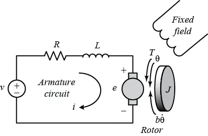
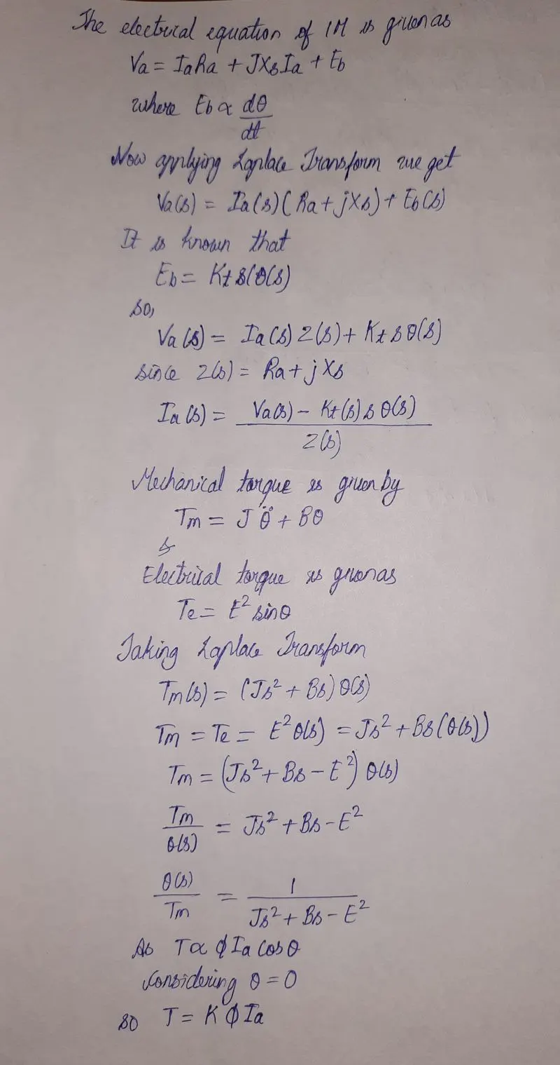
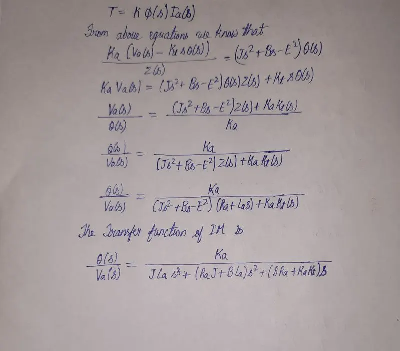
TRANSFER FUNCTION OF IM:
3. Model 3 phase induction motor with a 3 phase inverter using Direct Torque control using an Average Model, Implement both torque and flux control to achieve desired power.
Design Parameters:
- Initial Speed = 0 RPM
- Flux Target = 2.5 webers
- DC Voltage = 500 V;
- Fundamental Frequency = 60 Hz
- Speed Step Time = 0.01 secs
- Determine fundamental speed based upon fundamental frequency
- Determine the switching sequence for direct torque control
- Moment of Inertia = 0.1 Kgm^2
- Load Torque Initial = 0 Nm
- Final Load Torque = 50 Nm
- Torque Step Time = 0.03 secs
Motor Parameters: (Create an Average Model)
- Stator Resistance = 0.5 Ohms
- Rotor Resistance = 0.2 Ohms
- Stator Leakage Inductance = 20 mH
- Rotor Leakage Inductance = 10 mH
- Magnetizing Inductance = 200 mH
- Number of Poles = 4
- Torque to Speed
To acquire high enactment, Direct Torque Control (DTC) is a technique used in AC drive systems. In this paper, based on the hysteresis controller, a very simple improved DTC scheme is proposed for induction motor drive. Owing to its simple assembly & effective enactment, DTC is used for AC as well as DC drive as compared to other controlling schemes. the paper approaches mitigation of the ripples in torque by varying the predictable 3-level torque-hysteresis controller used in DTC. The expansion of distinctive switching approach has been generated for chosen voltage-vector. Based on ripple content simulation results carried out in MATLAB/SIMULINK for torque-hysteresis controller to minimize the ripples.
Direct Torque Controller
Direct torque control (DTC) is a technique that allows you to instantaneously control the motor magnetic flux and its electromagnetic torque in a decoupled way. Controlling the torque directly permits accurate static and dynamic speed regulation. The main components of the DTC subsystem are:
-
Flux and Torque Calculation — The stator flux linkage is estimated by integrating the stator voltages, and torque is calculated based on the estimated flux and the motor currents.
-
Speed Regulator — The regulator compares the actual motor speed with the speed reference and generates the torque reference.
-
Hysteresis Control — The calculated flux magnitude and torque are compared with the reference values. When the resulting flux or torque error crosses either the positive or negative hysteresis band value, a control signal is activated in order to correct the error.
-
Optimal Switching — Pulses to the motor inverter are produced based on the control signals generated by the hysteresis control and the stator flux linkage position.
The figure below illustrates the strategy used to determine the best voltage vector when the flux linkage is located in sector 0.
The image shows four cases:
-
V3 is selected when the electromagnetic torque should be increased and the flux should stay unchanged. Selecting the V3 voltage vector speeds up the flux and thus applies an acceleration torque to the rotor while slightly decreasing the flux magnitude.
-
V2 is selected when the electromagnetic torque should be increased and the flux should be increased. Selecting the V2 voltage vector slightly speeds up the flux and increases its magnitude.
-
V6 is selected when the electromagnetic torque should be reduced and the flux should be increased. Selecting the V6 voltage vector slows down the flux and thus applies a deceleration torque to the rotor while increasing the flux magnitude.
-
V5 is selected when the electromagnetic torque should be reduced and the flux should stay unchanged. Selecting V5 the voltage vector applies a deceleration torque to the rotor and slightly decreases the flux magnitude. Note that voltage vectors V1 and V4 are not selected in sector 0. Using these two vectors would have too much negative impact on the desired flux value. Finally, to keep the torque and the flux unchanged, the null voltage vectors V0 or V7 are selected.
When the flux linkage vector moves to sector 1, the selected voltage vectors become V4 for case 1, V3 for case 2, V1 for case 3, and V6 for case 4, and vectors V2 and V5 are not used. This 60 degree shift in the voltage vectors happens each time the flux linkage vector enters a new sector.
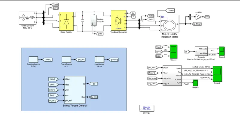
SIMULINK MODEL:
Electrical Model
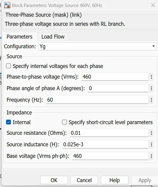
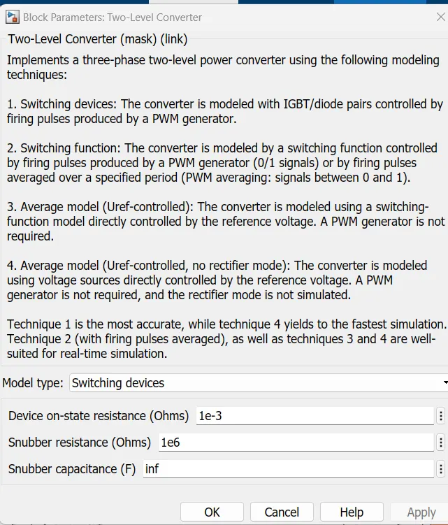
The electrical energy is supplied by a three-phase AC/DC diode rectifier connected to a 460 V, 60 Hz grid equivalent. The DC bus is connected to a three-phase, two-level converter. This converter generates the variable voltage and frequency required for variable-speed operation of the 150 HP induction motor. In addition, a braking chopper is connected to the DC bus in order to dissipate the kinetic energy of the motor during deceleration.
An inverter-fed induction motor drive can be controlled through various techniques depending on application, desired performance, and controller design complexity. Commonly used schemes are scalar control (V/Hz control or open loop flux control) or vector control (field-oriented control or direct torque control). This example uses a hysteresis-based direct torque control (DTC) technique.
Three Phase Input Source
Two Level Converter
Flux and Torque:
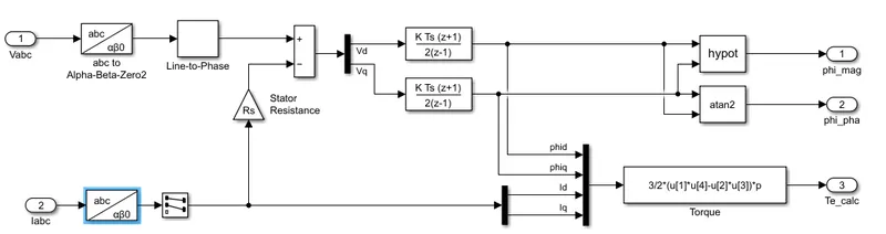
The stator flux linkage is estimated by integrating the stator voltages, and torque is calculated based on the estimated flux and the motor currents.
The 3phase Voltage and 3 phase current is converted from abc to Alpha-Beta-Zero and are given as input to Transfer function block. From two abc to Alpha-Beta-Zero blocks three output signals are created which are Phase magnitude, Phase angle and Torque.
SPEED REGULATOR:
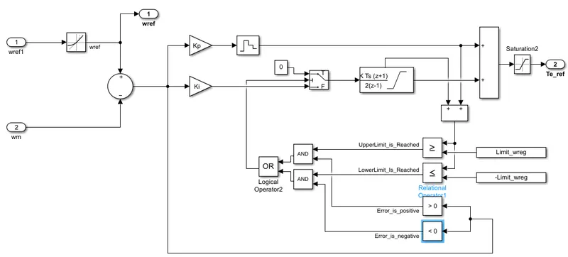
The regulator system compares the actual motor speed with the speed reference and generates the torque reference.
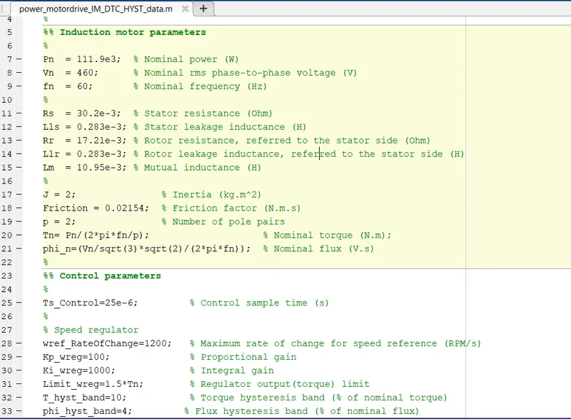
At 0.1 s, the speed reference is set to 1500 RPM and the motor starts to accelerate. The motor speed precisely follows the speed reference, whose maximum rate of change is limited to 1200 rpm/s. The 1500 RPM set point is reached at 1.35 s.
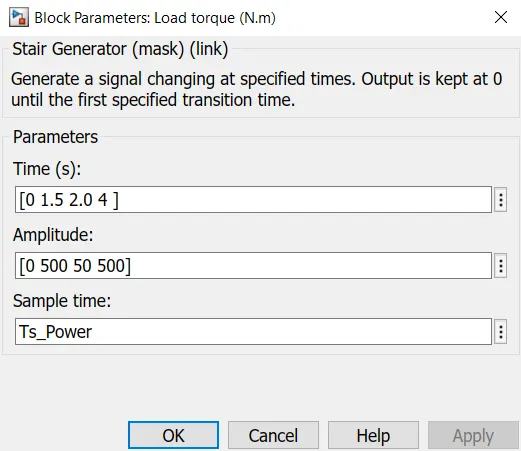
At 1.5 s, a load torque of 500 N.m is applied to the motor. The DTC control operates to maintain the motor speed at 1500 RPM.
At 2 s, the load torque is reduced to 50 N.m and at 2.5 s, the speed reference is reduced to 500 RPM. Observe on Scope 1 that the braking chopper operation dissipates the kinetic energy produced by the motor in order to avoid overvoltage on the DC bus. Finally, at 3.5 s, the flux reference is increased from 0.9 to 1.0 V.s.
OUTPUT:
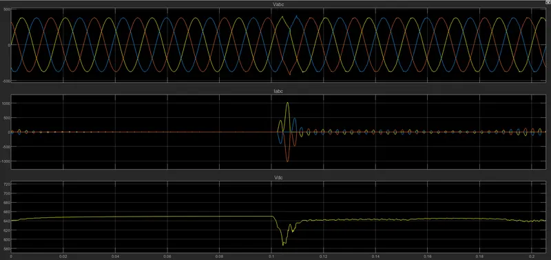
The above graph shows the Grid Voltage, Grid Current and DC voltage plot. The grid voltage has max value of 380V. At 0.1 sec when Motor RPM is incresed from 0 to1500RPM the grid current changes as there is peak current requirement from the motor when starting. The DC voltage is constant at 640V till 0.1sec but when motor is running the DC voltage drops and then settles at 640V.
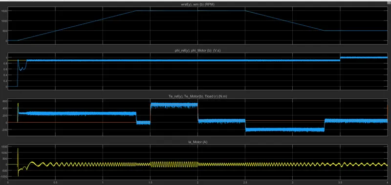
- The first plot shows the Motor RPM output. At 0.1Sec the RPM is increased from 0 to 1500RPM ad at 2.5seconds the speedc is reduced to 500RPM.
- The second graph shows the motor Angle_phiplot.
- The 3rd graph shows the Reference Torque, Motor Torque and Load Torque. The Motor Torque follows the Reference torque at 0.1seconds when 500Nm of torque is applied and at 1.35seconds the Reference torque is reduced near to 0 and Motor torque follows it. At 1.5s 500Nm of load torque is applied and at 2sec it is reduced to 50Nm and again at 4sec 500Nm of torque is applied and Motor Torque follows the Reference and Load torque.
- The last plot shows the Motor Current graph. When Motor starts at staring it draws high amount of starting current. At 0.1sec the motor current is increased to more than 1000A and later as the load torque the motor current oscillates between 160A to -160A.
CONCLUSION:
The Three Phase Induction Motor Drive is modelled and its speed is controlled using both the V/F Control method and Direct Torque Control Method and the Transfer Function of the Induction Motor is determined.