Project - 2 - Meshing on the suspension Assembly
Meshing on the suspension Assembly
Aim:
The aim of the project is to Volume Mesh and create connections for the Rear wheel Suspension Assembly model.
Procedures:
1.Geometry Cleanup
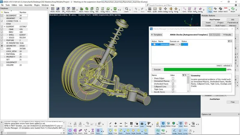
The Rear wheel suspension Assembly model is loaded into the ANSA GUI using the “File > Open” command then the models is observed in different views using the functions keys. Following that the model is checked for geometry errors using “Check’s Manager > Geometry” command, in case of geometry errors such as missing cons can be corrected using “Hot Points > Insert” command in TOPO module
2.Topology
After the model’s geometry is corrected for all errors, the topology is performed for broken faces using “Faces>Topo” command in the topology module.
3.Mid-surface
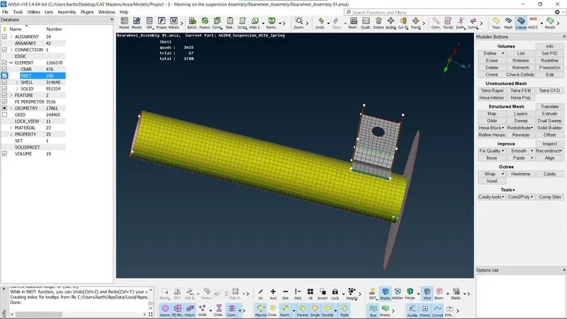
Once the model’s topology is complete the mid surface is created for 3 components as per the models faces using the “Faces>offset>Visible” or “Faces> Mid-surface> Casting >Select” command. The thickness off the mid-surface is assigned as same as each of the parent geometry faces which is 3mm.
4.Material Assignment
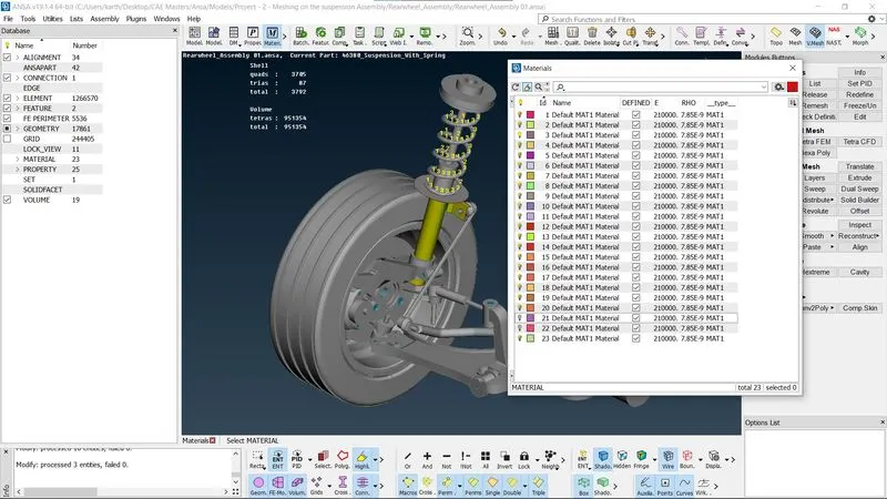
The Material for the components as assigned as listed in the image below.
5.Property Assignment
The Property for the mid-surface is applied as same as the models’ other faces corresponding to their material properties. Therefore, the model is ready for meshing. The module is switched to meshing. This is done using Set PID command in “Topo> Faces > Set PID > Faces/ shells”
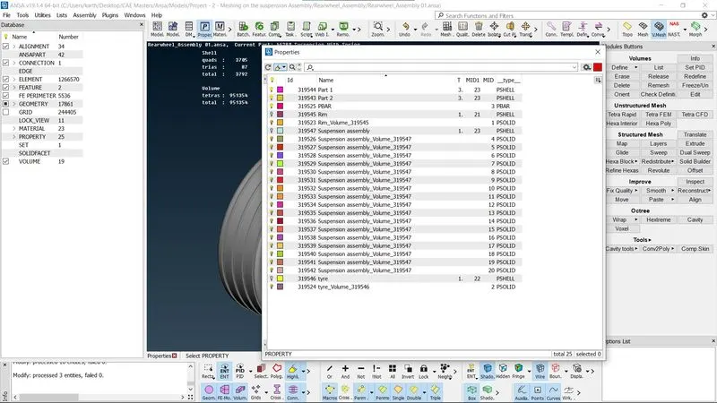
As for the thickness of the 3 components in the suspension assembly it is assigned according to the parent geometry at 3mm. The Solid property is assigned for the rest of the surface mesh during the Volume Mesh at a total of 19 Solid Components.
6.Mesh Length
Before beginning the meshing process the model is checked for the length between the two hot points since the require length is 6.5mm for the tire and rim and 4mm for the rest of the geometry so using “Perimeter> Length>Perimeter” and “Perimeter> Length>Macros” commands in the Mesh Module it is set to 6.5mm and 4mm with respect to the entire model.
7.Quality Criteria
The assigned quality criteria are set for the mesh as per given below:
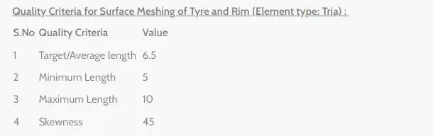
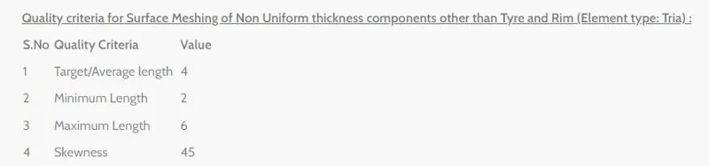

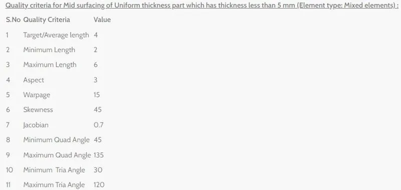
After assigning the above quality criteria the model is checked for any errors if any is corrected using the above-mentioned methods again and again until the model is appropriate for meshing.
8.Meshing
Now in the mesh module using the “Mesh> Best Mesh> Select” command the selected part of the geometry is surface meshed as per the requirements. Once the meshing of the entire model is done the locations withs trias are identified and it is reconstructed.
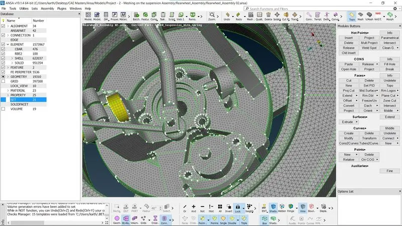
9.Swap, Split and Join
In the mesh the opposite tiras are swapped using the “Elements > swap” command and the trias are split using the “Elements >Split” command. in case of nearby trias they are joined using the “Elements>Join” command.
10.Spot Mesh
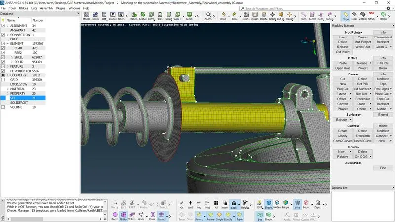
With “Mesh>Spot Mesh > Select” command the unmeshed macros are meshed after making the changes in the parent geometry using ‘Extend’ and ‘Intersect’ command in the Topo module.
11.Reconstruction of Mesh
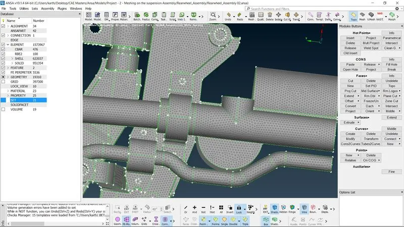
After using Swap, Split and Join commands on the mesh it is reconstructed using the “Shell Mesh>Reconstruct” command along with Reshape and Smooth. Following that the mesh should be checked so that any deviation form parent geometry can be rectified.
12.Quality and geometry check
Once again, the quality and geometry of the model is checked using the checks manager in Geometry and quality criteria as per the given instructions.
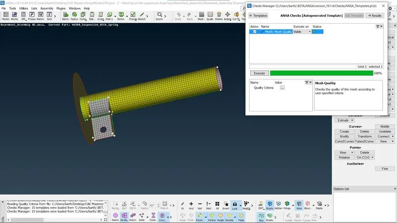
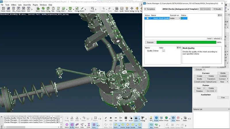
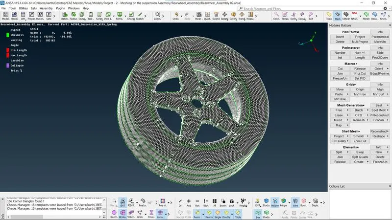
The model is reshaped and reconstructed as many times as possible up until the off elements becomes zero so, post which we can start Volume meshing.
13.Volume Mesh
The volume mesh is done by defining each part as individual volume and assigning properties the using the “Volume >Define> Auto Detect” command and Meshed using “Volume >List> Selection of volume > Type of Unstructured Mesh (Tetra Rapid or Tetra FEM)”
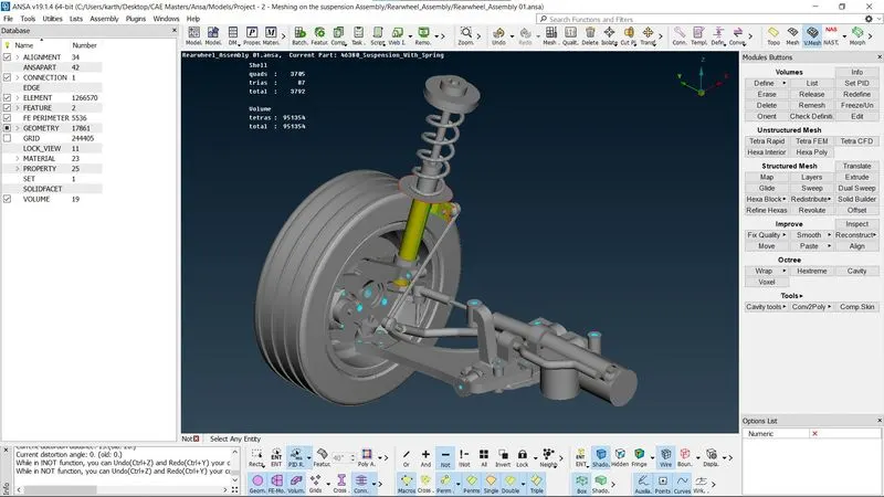
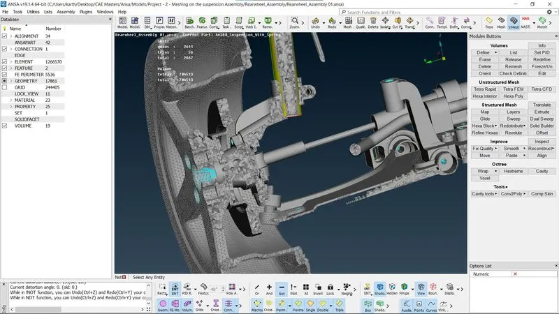
14.Reconstruction of Mesh
With respect to the Tet Collapse 0.2 the Volume mesh is reconstructed and fixed for quality for all 19 solid components according to the parent geometry.
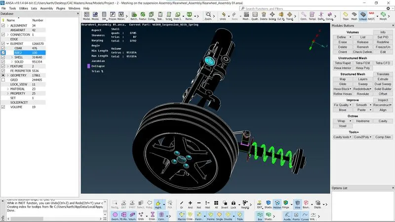
15.Connections for Bolts
The bolt holes are identified and the bolt connection is made by using cluster of nodes by the "NASTRAN module > Elements > RBE2>Many Nodes>Select nodes>Ok> Finish" and then by using “Elements > RBE2>Two Nodes>Select nodes>Ok> Select Part> Finish”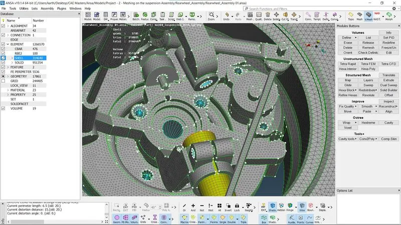
16.Connection for Support Hinge
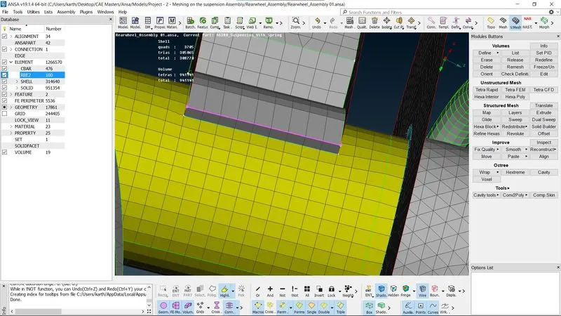
For creating connection between two 2D mesh ‘Overlap Shell’ connection is used by creating a curve and converting it into seamline which is then selected using Connection manager and an Seamweld connection is created between the two surfaces with only Primary Row.
17.Connection for Suspension Assembly
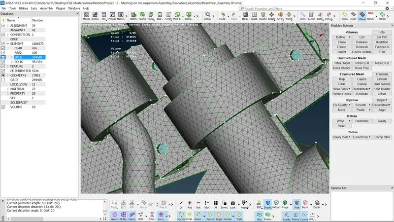
The Connection for the various parts in the suspension Assembly is connected by the using cluster of nodes RBE2 and Two nodes RBE2 by the following commands such as connection is made by using cluster of nodes by the "NASTRAN module > Elements > RBE2>Many Nodes>Select nodes>Ok> Finish" and then by using “Elements > RBE2>Two Nodes>Select nodes>Ok> Select Part> Finish”
18.Connection for Solid Component Intersection in Suspension Assembly
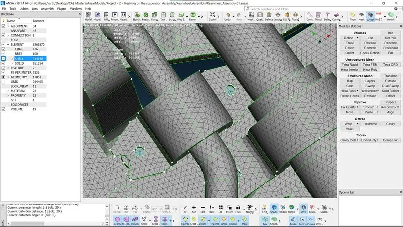
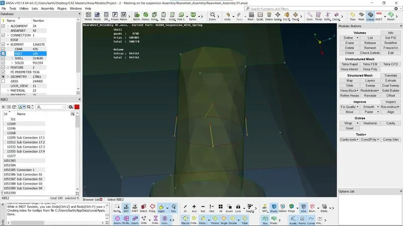
In case of solid components passing a hole on another solid component the connections are made as four distinct Two Node RBE2 as shown in the image.
19.Representation of Spring as 1D-bar element
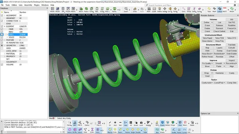
For representing the Spring as 1D-bar element first a middle curve is generated for the spring then it is connected as one single curve. A On COG point is created with respect to the curve. Now In NASTRAN module by following the command “Elements > CBAR> Select Orientation with Node> Curve(box)>Select curve>ok>Select orientation node created > Element Length(3mm)>PBAR(Radius(5mm))> CBAR (Part name)> OK” 1D bar elements will be created for the spring.
20.Connection for Rim with the Suspension Assembly
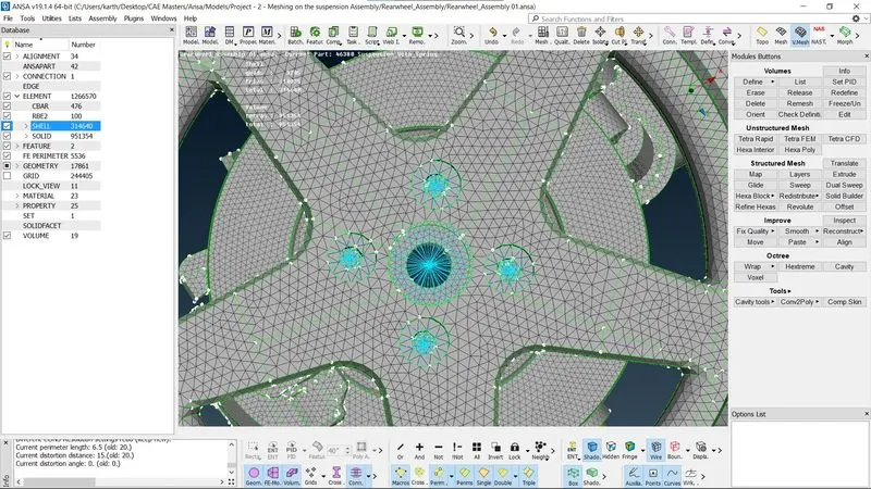
The connection between the Rim and the base of the suspension Assembly is made by using cluster of nodes by the "NASTRAN module > Elements > RBE2>Many Nodes>Select nodes>Ok> Finish" and then by using “Elements > RBE2>Two Nodes>Select nodes>Ok> Select Part> Finish”
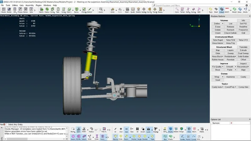
Final Model is ass shown in the image below
Learning Outcomes:
The model has a lot of parts with varying thickness such as molded parts so the trias fully used for surface meshing. In this challenge I learned how to check the geometry for errors and fix it and how to generate faces for missing locations and performing topology on the model. Along with this the mid-surface creation for faces and assigning property and thickness is learned and post this the Mesh generation and Quality fixing according to the Quality criteria is learned following that Volume Meshing along with creating Connections for the solid model is learned from this challenge.
Conclusions:
Thus, Rear wheel Suspension Assembly model is volume meshed by creating a good geometry with fine topology along with mid-surfacing and fine Surface Mesh is performed on the model. After completing this the model geometry checks the model is meshed as tria elements. Post the Volume Meshing along with creating Connections for the solid model are completed.