Project - 2 - Meshing on the suspension Assembly
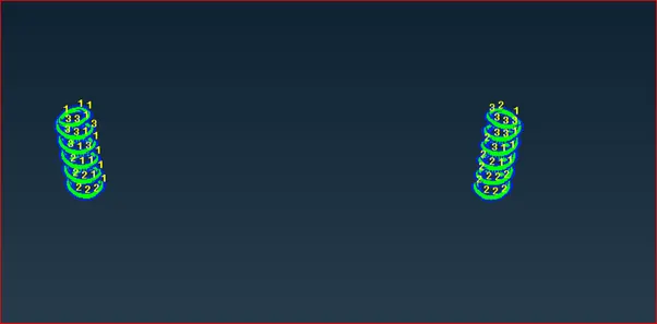
AIM: To the given assembly, check for the geometrical errors and mesh with the given element Quality criteria. After meshing the component the thickness has to be assigned for mid surfaces. Use tetra elements to model non-uniform thickness components. Also use Appropriate connections to connect the component as suggested in the Project-2 video (Use PBAR elements to model suspension spring). At last perform Symmetry command to reflect the half-finished model to the other side.
SOFTWARE USED: ANSA V 19.1.5 (Here v means version).
ABOUT ANSA: ANSA is developed by BETA CAE systems, ANSA stands for Automatic Net Generation For Structural Analysis. It is a pre-processor tool.
ANSA PHASES:
- Import a cad model
- Geometry clean-up
- Skin/mid surface generation
- Shell or solid meshing
- Elementary quality check
- Mesh improvement
- Apply load and boundary conditions
- Export input file.
Import a cad model: This is the first step in Ansa, Ansa reads some file formats if in case the file format is not in Ansa readable, the Ansa automatically converts that file format into Ansa readable.
The file formats readable by Ansa is
1) (*.step/*.stp/*.STEP/*.STP)
2) (*iges/*.igs/*.IGES/*IGS/)
3) (*.STL/*.stl)
2) Geometry clean-up : It checks the cad model if it have any geometrical issues like , sharp edges, holes, triple cons, single cons etc.
3)Skin/mid surface generation: In this phase we need to create mid surface by using some techniques like offset / middle/ mid surface automatic , manual.in this project it consist of uniform thickness components and non-uniform thickness components also and also spring.
- If the thickness is less than 5mm – shell meshing.
- If the thickness is greater than 5mm – solid meshing.
- If in case springs are present we need to take the mid by using some procedure.
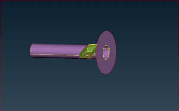
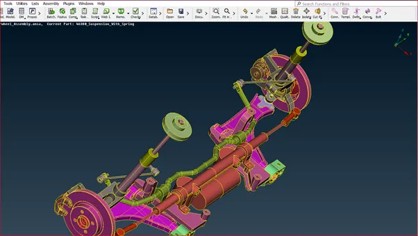
Below figure represents the uniform and non-uniform components and spring.
First figure represents the uniform thickness component in this rear wheel assembly.
Below figure represents the non-uniform thickness components.
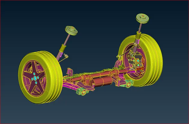
Another figure for better understanding.
Below figure represent the c bar element of a spring.
For the first figure I took mid surface because it has uniform thickness.
For the second figure I took volume meshing for remaining all components.
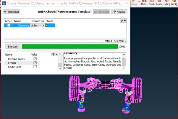
Before going to that check for geometry.
I resolved all the issues related to geometry clean up. Below figure represents the geometry clean up execution.
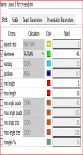
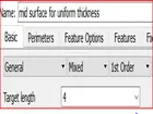
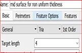
Then I will go to meshing part. Here for uniform thickness components I used mixed element mesh. For non-uniform components I used tria for plane surface and ortho tria for where the curves are present, because of better feature capturing. Below figure represents the support team menctioned criteria.
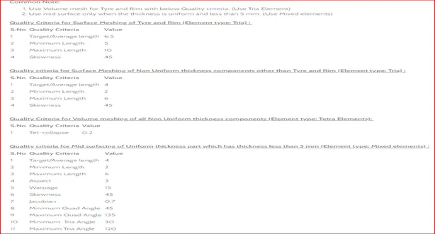
According to their requirement I put the values in quality criteria.
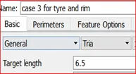
Below figure represents the quality criteria photos for each method.
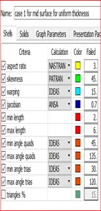
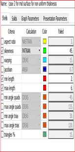
After meshing is done the component is looking like below figure.
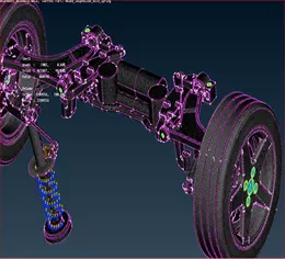
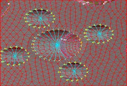
RESULT : For tyre and rim I provided result separately and remaining for others also like that. I provided the connections where is required rbe2,rbe2 2 node, overlap shell connections ,above figure shows the connections.
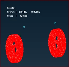
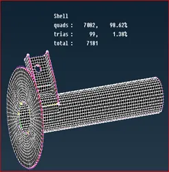
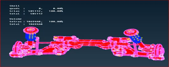
After completing the meshing I done transform option for symmetry.
There is no off elements and zero Tet collapse.
- Surya Teja GarimellaFeel free to go through the projects and ask if you have any doubts.