Project - 2 - Meshing on the suspension Assembly
Project - 2 - Meshing on the suspension Assembly
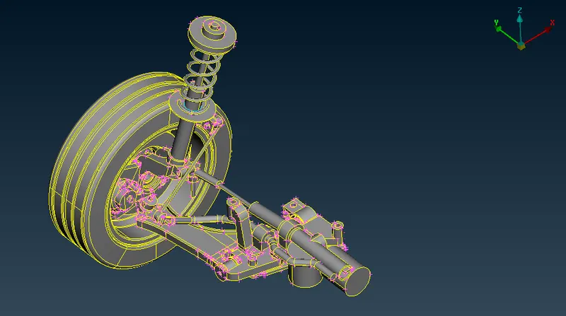
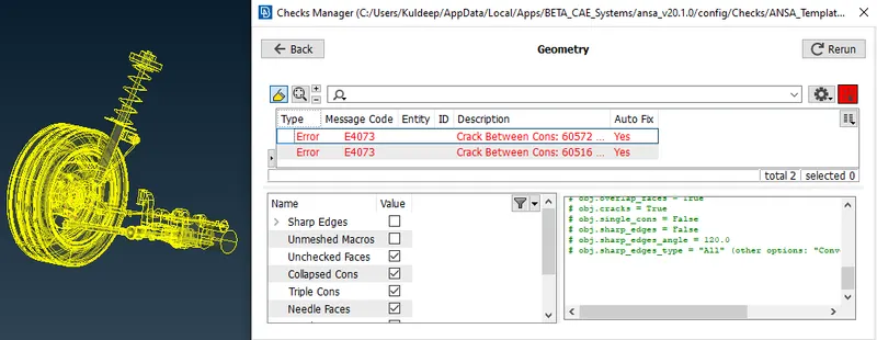
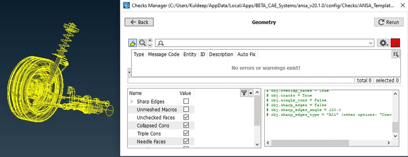
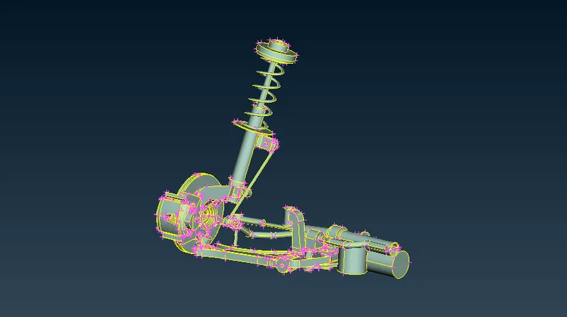
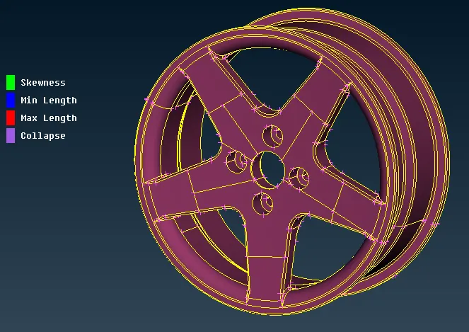
Initially, we have these three PID for rim, tyre, and suspension assembly. We do not require mid so we start doing defeaturing for the surface mesh, while this has to capture the feature area properly.
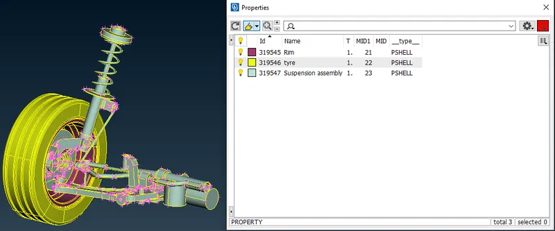
First, we choose the suspension assembly in this we have only volume mesh as there is no separate component with thickness less than 5mm. For the curve region, we use ortho-tria while for the flate region we use only tria to get batter feature capturing.
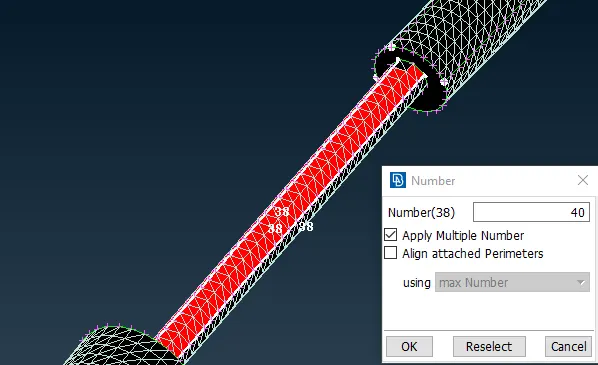
In this, the rod element fails for maximum element length so we increase the node from 38 to 40 and then erase the older mesh and put another orthotria mesh which went well.
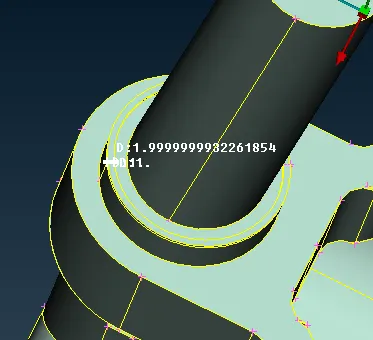
In several region, we could not avoid the off element as we can not compromise with some important surface features.
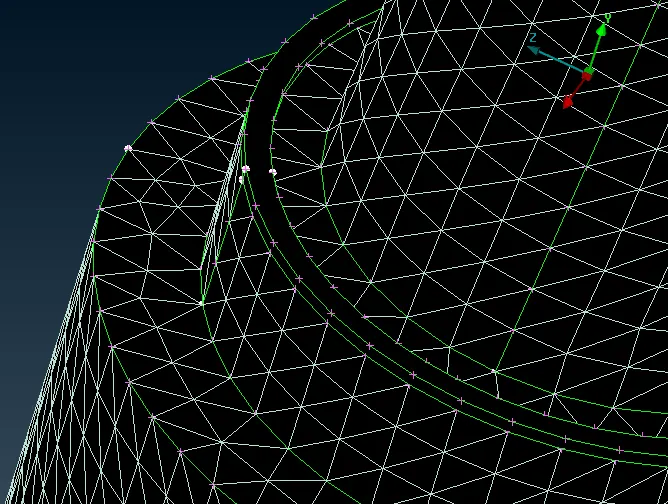
For batter mesh flow we first mesh the curved surfaces of part with orthotria and after clearing all the quality for this then we do tria mesh for all the remaining unmeshed surfaces in one shot. It saves out time and does not disturb the orthotia mesh.
As there are several off-element remaining that we can avoid capturing those critical areas of the part.
Now we will go to the volume deck and do the following steps-
- First, define a closed volume.
- Create a new PSOLID property for that part.
- Perform tetra rapid or tetra FEM volume mesh.
Surface meshing
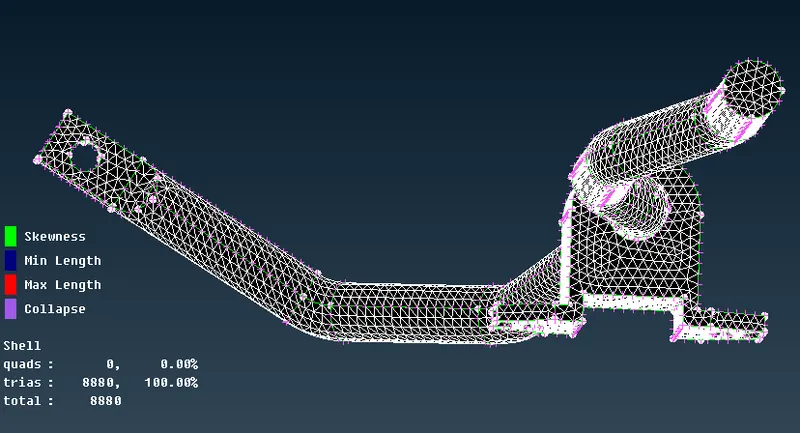
Defining a volume that is still with unmeshed status.
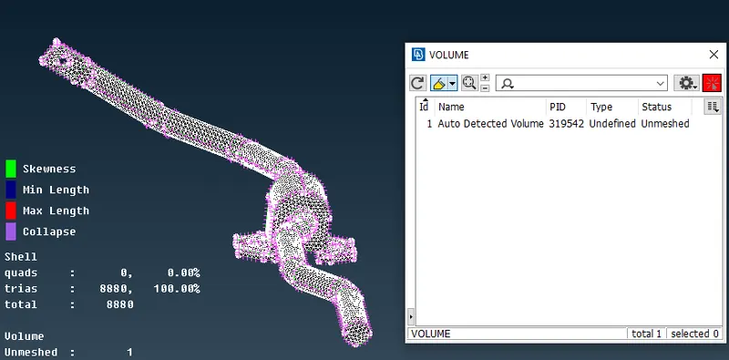
We generate volume with both ways-
Tetra FEM
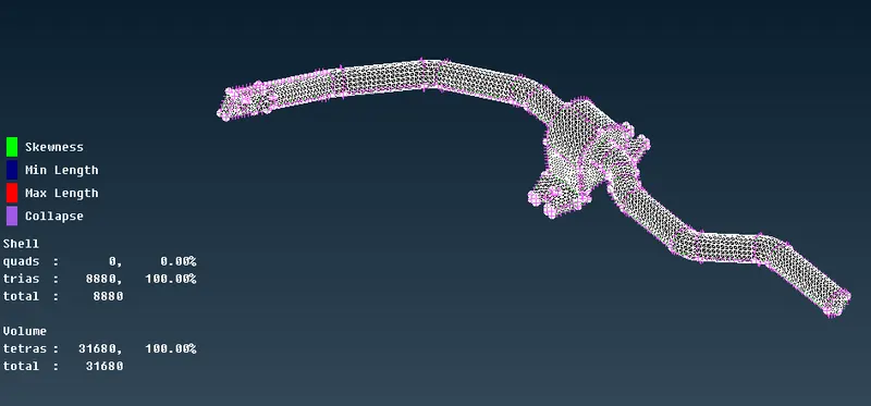
Tetra Rapid
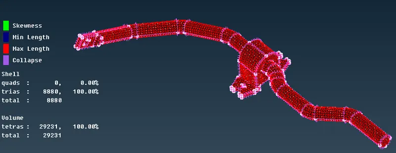
Here from both volume techniques, we can say that they have the same results however the tetra rapid produces less ny=umber of tetras as compare to tetra FEM.
In this above-generated volume, we can see that there is no off element and if there are any then we can remove that by the fix quality option. In this volume, we have only tetras and no quads which have to be maintained throughout the model. Once we are done with generating a volume of one part and clear all quality only then we should move to the next adjacent part.
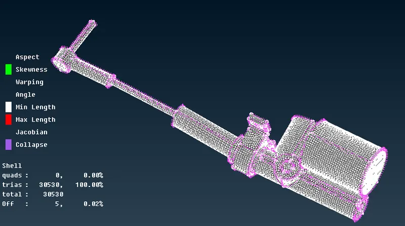
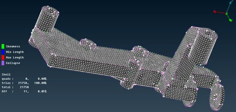
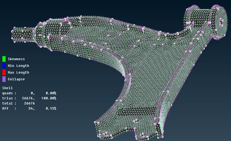
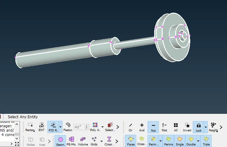
Similarly, we will follow the same method to generate the volume for the above-meshed shell meshed elements.
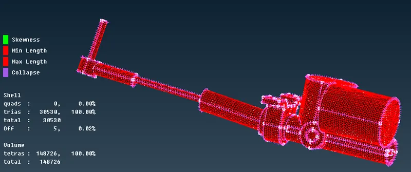
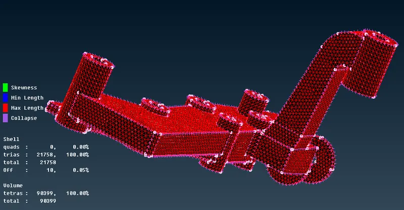
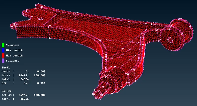
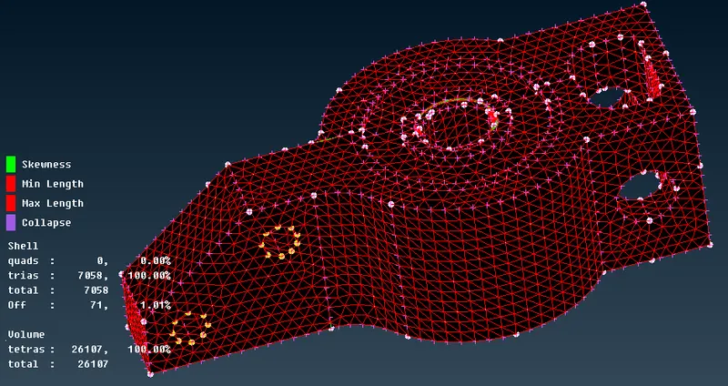
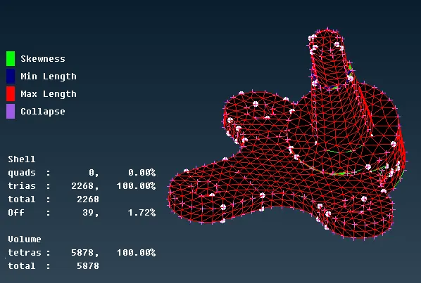
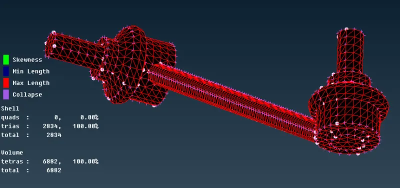
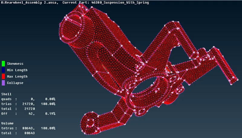
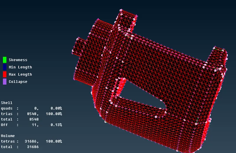
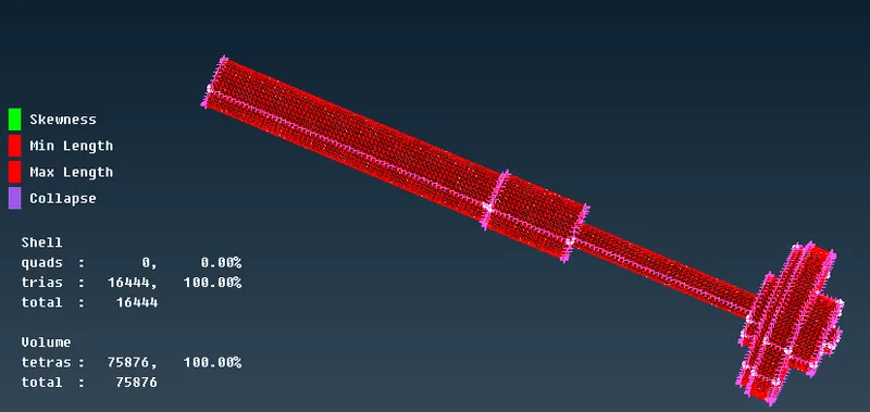
So far we have completed the volume mesh for suspension assembly and now we are moving to complete the meshing of the sheet metal part which has a thickness of less than 5mm. We took mid-surface using the offset surface.
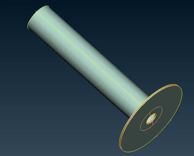
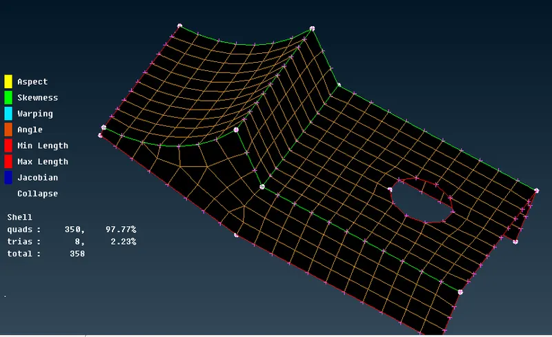
The meshed mid surface of sheet metal part
For the tyre we have different mesh and quality parameters so for that first load them into ANSA.
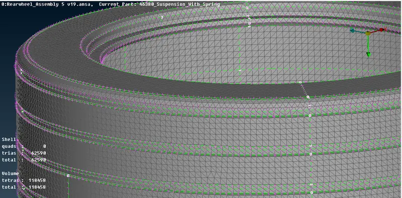
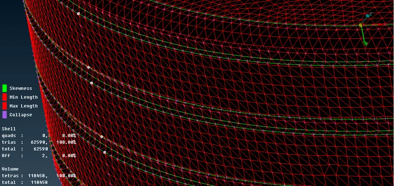
Measure to identify the areas which have less than 5mm thickness. This groove region is not recommended to defeature or suppress the lines as it is a very important feature of tyre.
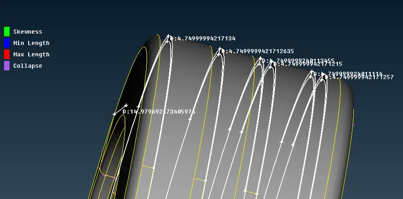
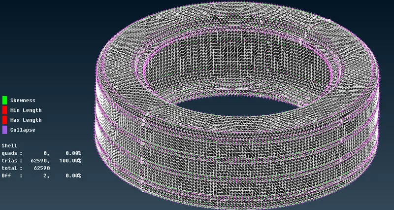
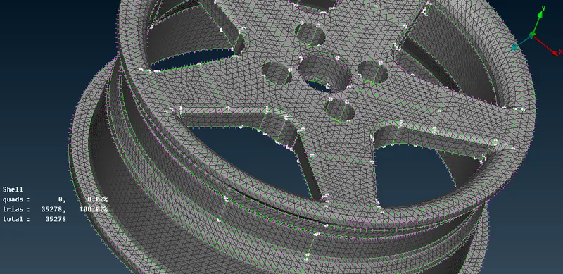
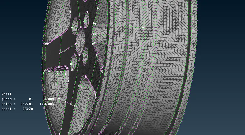
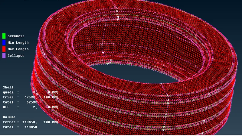
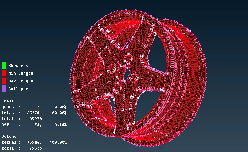
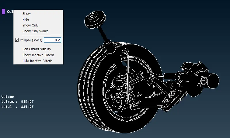
Volume meshes with no tet collapse for 0.2 collapse limit.
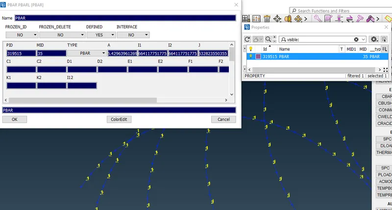
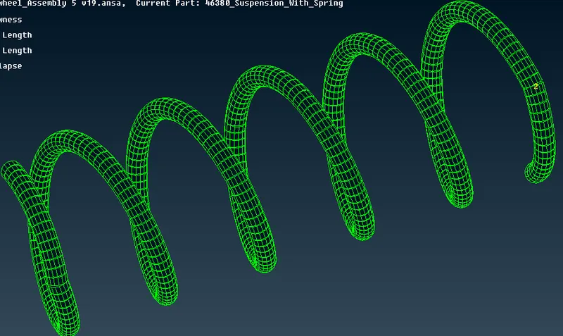
Suspension spring, we model it as PBAR element.
We took the curve middle and represent the spring with a curve line.
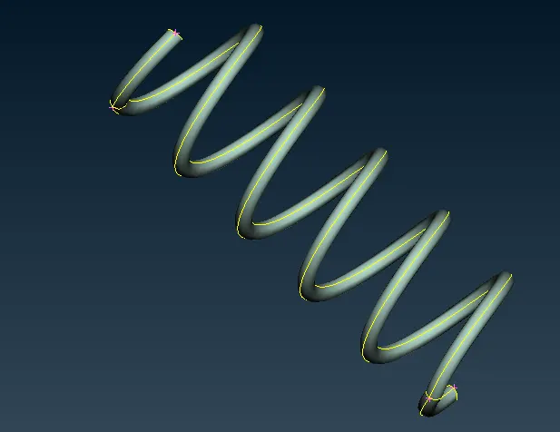
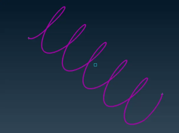
In NASTRAN Decks we model it now as a CBAR. Here we check the orientation with a node in the curve (seq.) and middle click.
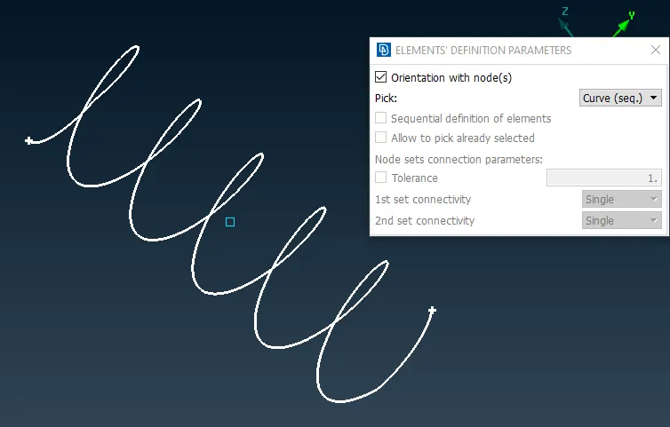
Create a COG point and then select it and give the element length as 4mm.
In this PBAR card, we gave the radius as 5mm to calculate the area and moment of inertia.
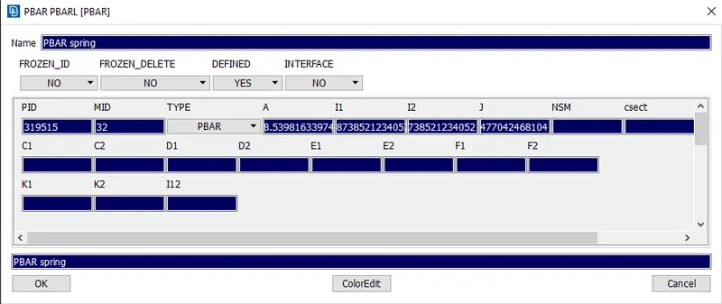
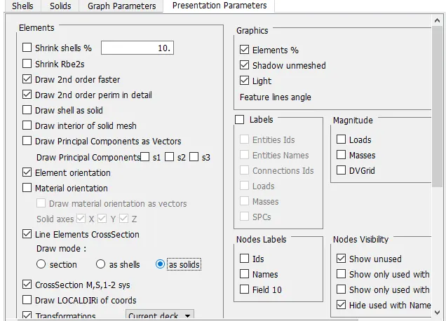
In this, we check LINE ELEMENT CROSSESECTION as solid.
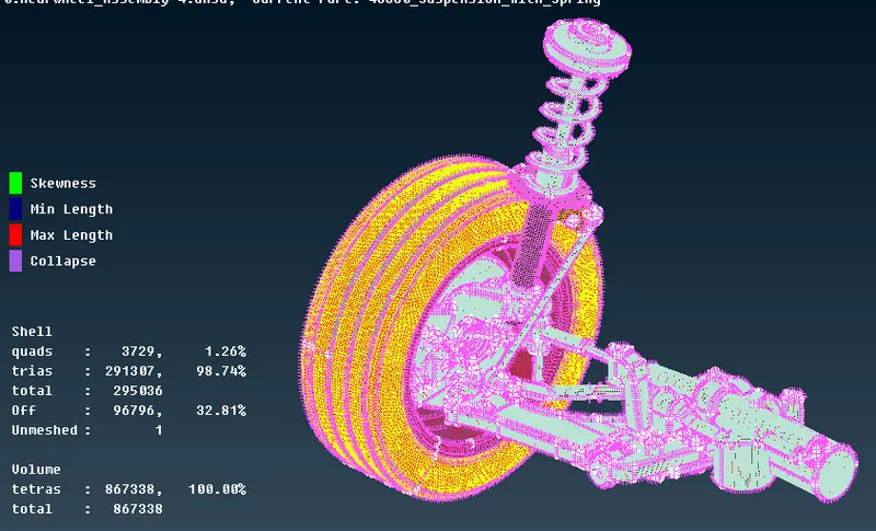
Here we have a complete volume meshed model with no tet collapse.
Now we have to do the connection, as the connection information is not given here we will do mostly the rigid connection. In areas where a bolt and steam connection required we do it by creating 2 cluster RBE2 and then connect their master node with 2 nodes REB2 connection as bolt definition.
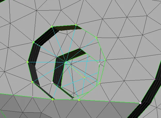
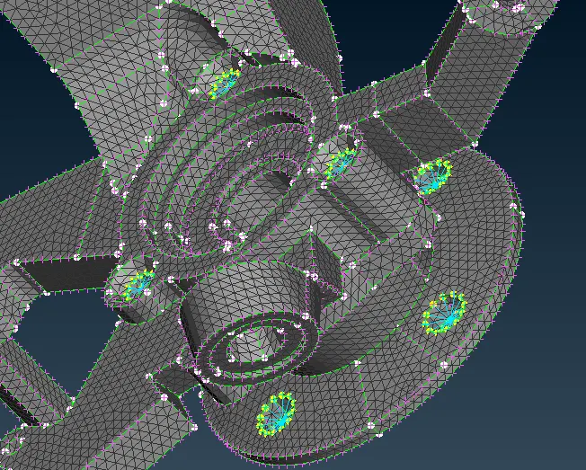
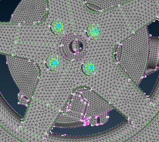
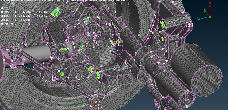
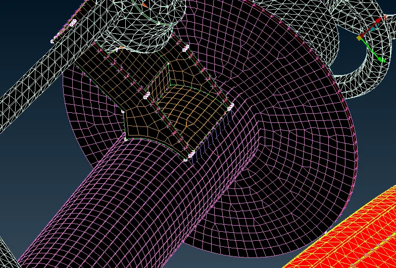
Here we did a seam weld connection by creating a curve in that region and then convert it into a seam weld connection. After that in the connection manager chooses the p1, p2, and connection type as OVERLAP SHELL as the parts are parallel to each other.

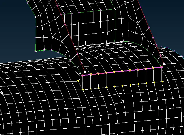
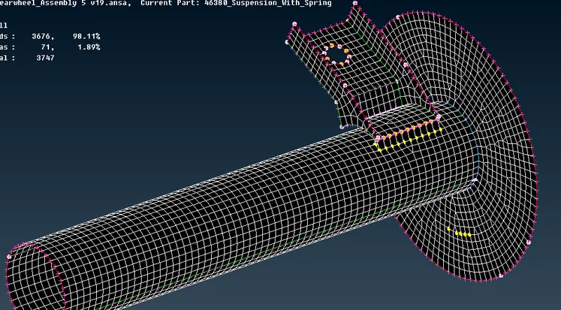
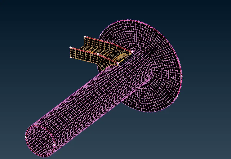
Here we draw shell as solid
Learning Outcomes:
Now we can work on more complex areas for defeaturing and able to perform shell and solid mesh.
Learn to establish the connection in a suspension assembly.
Got more confidence in shell and solid part modeling.
Conclusion:
We have successfully completed the modeling of tyre, rim, and suspension assembly along with different types of seam welding and rigid connection.
Project Link:
https://drive.google.com/file/d/1cnEgdfeXEy4ghgW23aoNEomOazlVDly2/view?usp=sharing
https://drive.google.com/file/d/1cnEgdfeXEy4ghgW23aoNEomOazlVDly2/view?usp=sharing