Tetra and Shell Meshing for the Suspension System and Wheel Assembly
AIM :-
Tetra and Shell Meshing for the Suspension System and Wheel Assembly
ABSTRACT :-
The objective of the project is to perform meshing on the components of the suspension and wheel assembly. The components below 5 mm thickness is to be captured with the shell meshing technique and those above the 5 mm or solid parts is to be captured with the 3D tetra mesh techniques. The coil spring in the model is to be captured using 1D element (bar element). Once after performing the shell and tetra mesh operation we have to deploy the required connection data between various components to make the proper connectivity between them to assure that there no free parts in the model.
METHODOLOGY :-
To capture the geometry we need to follow these steps :-
1. Import geometry & Check for Topological cleanup.
2. Segregation of all parts under different property ID.
3. Quality parameter and Mesh parameter setup.
4. Defeaturing of the construction lines in the parts.
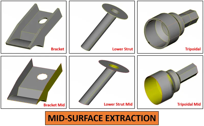
5. Mid-surface extraction if the components with a uniform thickness of less than 5 mm.
6. Shell meshing, mesh correction and 1D element deployment for coil spring.
7. Volume definition and 3D mesh generation for other than mid-surfaced components.
8. Implementation of connections at required areasa and assignation of the shell thickness and bar element as solid.
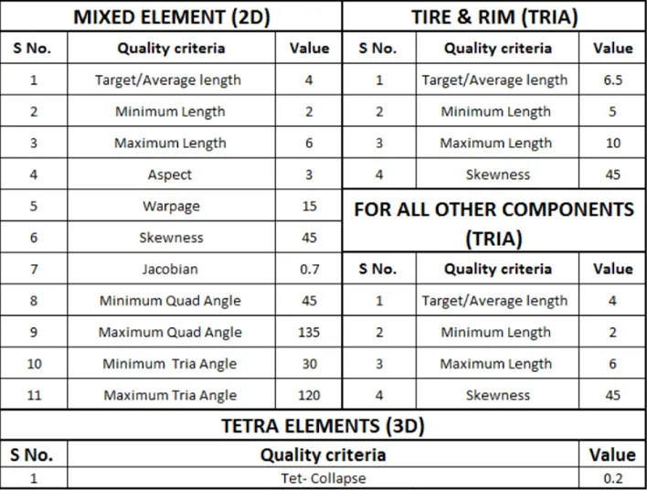
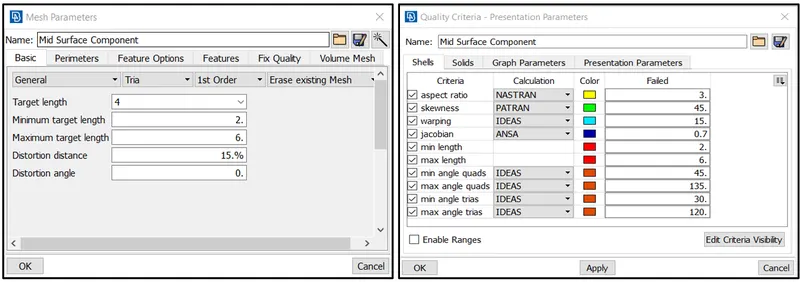
Quality Criteria for Surface Meshing of Tyre and Rim (Element type: Tria) :
#INTRODUCTION
Vehicle Suspension System
The suspension system must provide proper steering control and ride quality. Performing these functions is extremely important to maintain vehicle safety and customer satisfaction. For example, if the suspension system allows excessive vertical wheel oscillations, the driver may lose control of the steering when driving on an irregular road surface. This loss of steering control can result in a vehicle collision and personal injury. Excessive vertical wheel oscillations transfer undesirable vibrations from the wheel(s) to the passenger compartment, which causes customer dissatisfaction with the ride quality. The suspension system and frame must also position the wheels and tires properly to provide normal tire life and proper steering control. If the suspension system does not position each wheel and tire properly, wheel alignment angles are incorrect and usually cause excessive tire tread wear. Improper wheel and tire position can also cause the steering to pull to one side.
When the suspension system positions the wheels and tires properly, the steering should remain in the straight-ahead position if the car is driven straight ahead on a reasonably straight, smooth road surface. However, if the wheels and tires are not properly positioned, the steering can be erratic, and excessive steering effort is required to maintain the steering in the straight-ahead position. The steering system is also extremely important to maintain vehicle safety and reduce driver fatigue. For example, if a steering system component is suddenly disconnected, the driver may experience a complete loss of steering control, resulting in a vehicle collision and personal injury. Loose steering system components can cause erratic steering, which causes the driver to continually turn the steering wheel in either direction to try and keep the vehicle moving straight ahead. This condition results in premature driver fatigue.
The suspension system contains three major parts: a structure that supports the vehicle’s weight and determines suspension geometry, a spring that converts kinematic energy to potential energy or vice versa, and a shock absorber that is a mechanical device designed to dissipate kinetic energy.
An automotive suspension connects a vehicle’s wheels to its body while supporting the vehicle’s weight. It allows for the relative motion between the wheel and vehicle body; theoretically, a suspension system should reduce a wheel’s degree of freedom (DOF) from 6 to 2 on the rear axle and to 3 on the front axle even though the suspension system must support propulsion, steering, brakes, and their associated forces. The relative motions of the wheels are its vertical movement, rotational movement about the lateral axes, and rotational movement about the vertical axes due to the steering angle.
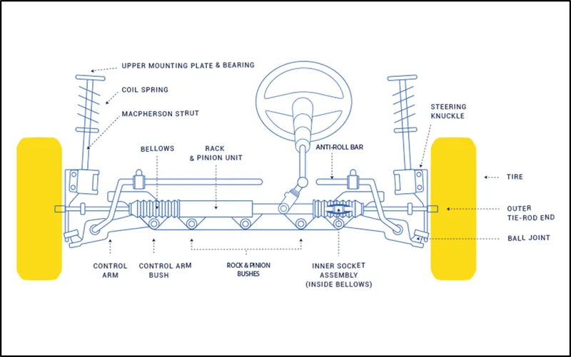
Types of Suspension System
1) Independent suspension system
This system means that the suspension is set-up in such a way that allows the wheel on the left and right side of the vehicle to move vertically independent up and down while driving on an uneven surface. A force acting on the single wheel does not affect the other as there is no mechanical linkage present between the two hubs of the same vehicle. In most of the vehicles, it is employed in front wheels.
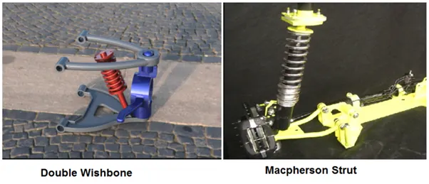
This type of suspension usually offers better ride quality and handling due to less unsprung weight. The main advantages of independent suspension is that they require less space, they provide easier steerability, low weight, etc. Examples of Independent suspension are
- Double wishbone
- Macpherson strut
2) Dependent Suspension System
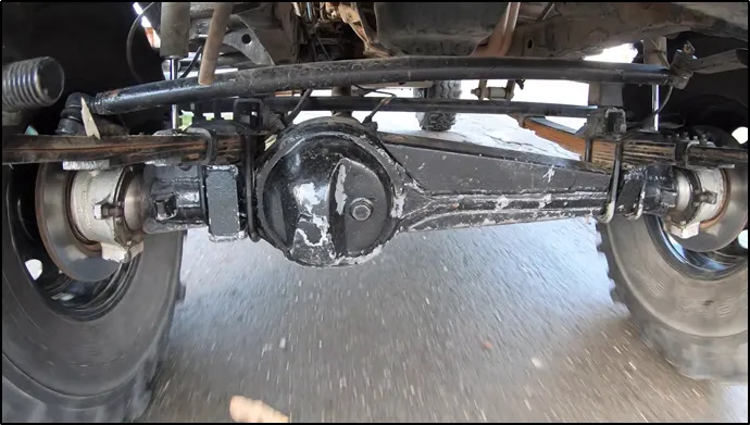
In Dependent Suspension there is a rigid linkage between the two wheels of the same axle. A force acting on one wheel will affect the opposite wheel. For each motion of the wheel caused by road, irregularities affect the coupled wheel as well. It is mostly employed in heavy vehicles. It can bear shocks with a great capacity than independent suspension. Example of this system is
a. Solid Axle Suspension
3) Semi-Dependent Suspension System
This type of system has both the characteristics of a dependent as well as independent suspension. In semi-independent suspension, the wheel move relative to one another as in independent suspension but the position of one wheel has some effect on the other wheel. This is done with the help of twisting suspension parts. Example of semi-independent is
a. Twisted Beam
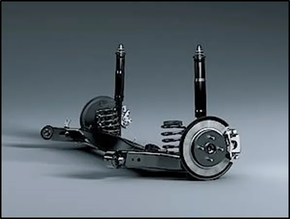
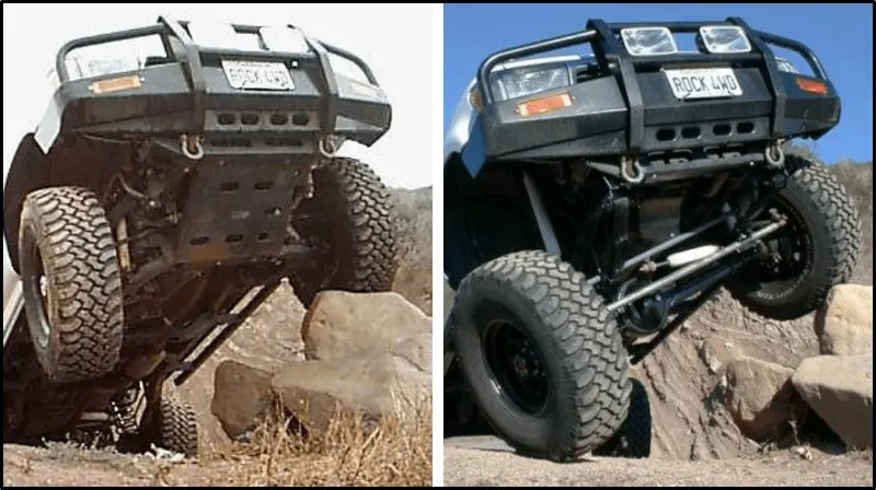
The difference between the dependent and independent suspension can be easily identified from the below image,
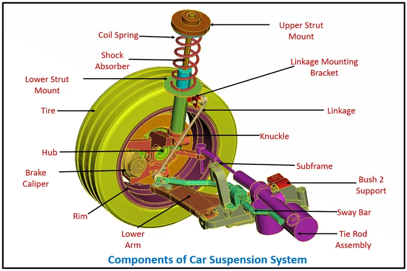
#Components of Car Suspension System :-
Steering Knuckles
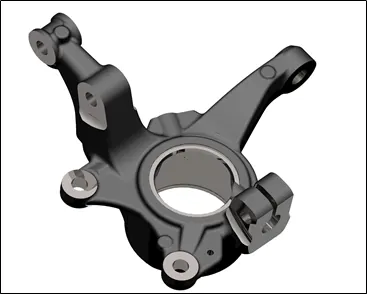
Steering knuckles support the wheel and tire, brakes, and sprung weight of the vehicle. A steering knuckle can be mounted in a variety of way for both front and rear suspensions. Figure shows an example of a common steering knuckle configuration. The steering knuckle also has an attachment point for the outer tie rod end. A wheel bearing or set of bearings mount to the steering knuckle to provide the mounting of the wheel hub. Steering knuckles are also sometimes called spindles. The spindle portion of the steering knuckle is where the wheel bearings and brake components are mounted. The spindle supports those components and allows the wheel to rotate on the wheel bearings.
Lower Arm
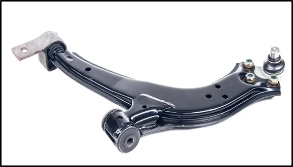
Control arms are used to control wheel movement. Used on both front and rear suspensions, they are commonly referred to by their position, such as the upper and lower control arms. Common control arm configurations are shown in figure above. Control arms are also called A-arms or wishbones due to their similarity to being A- or wishbone-shaped. A-arms typically have two connections to the frame and a ball joint for connecting to the steering knuckle. The control arm mounts to the frame with bushings. These bushings allow for up and down movement of the arm while controlling back and forth motion.
Ball joint
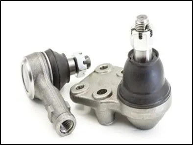
Ball joints allow the steering knuckle to pivot for steering while providing a tight connection to the control arms and preventing any unwanted up and down or sideways movement. Ball joints use a ball-and-socket joint to allow a wide range of motion, similar to a shoulder or hip joint. Ball joints are of two types,
1) Load carrying ball joints.
2) Non-load carrying ball joints.
Load-carrying ball joints support the weight carried by the springs. Because of this, these joints tend to wear faster and need replacement more often than non-load-carrying joints.
Non-load-carrying joints provide a steering pivot and component connection with a wide range of movement just like load carrying joints, but without the sprung weight applied to them.
Hub
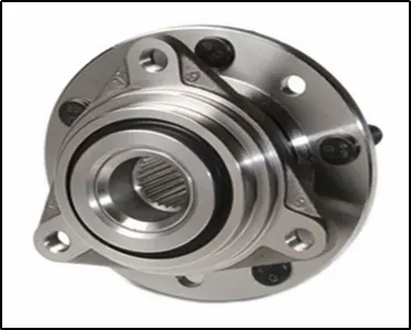
Wheel hubs must provide a secure mounting surface for the wheel rim and tire assembly. Wheel hubs also contain the wheel bearings that provide smooth wheel rotation with reduced friction. Wheel bearings must have a minimum amount of end play to greatly reduce wheel lateral movement. The wheel hub and bearing assemblies must carry the load supplied by the vehicle weight, and these assemblies must also guide the wheel and tire assembly.
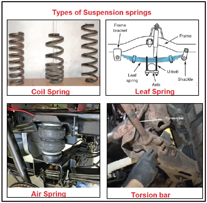
Coil Spring
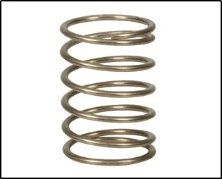
The springs in the suspension have two important functions. Springs support the vehicle weight and absorb the bumps and movements that occur when driving.
There are four types of springs used in suspension systems
- Coil spring
- Leaf spring
- Air spring
- Torsion bar
Shock Absorber
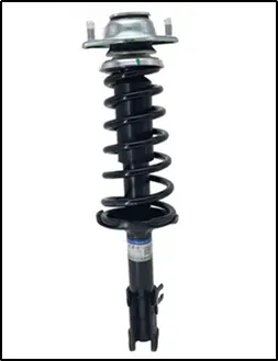
Shock absorbers are actually dampers, meaning that they reduce or make something less intense. The springs do the shock absorbing while the shocks dampen the spring oscillations. Without the shock’s absorber, our vehicles would continue to bounce for a long time after every bump, dip, and change in body movement.
The most common type of shock absorber is the direct double-acting hydraulic shock absorber. This means that the shocks are used to directly act on the motion; double-acting means that they work in both compression and extension modes, and hydraulic means that fluid is used to perform work. Compression is upward wheel travel, also called jounce. The extension is downward wheel motion and is also called rebound.
PROCEDURE :-
#Import geometry & Check for Topological cleanup
First task we perform before topology cleanup is we import the assembly model in the ANSA user interface. As soon as we import the geometry we see the model as shown below.
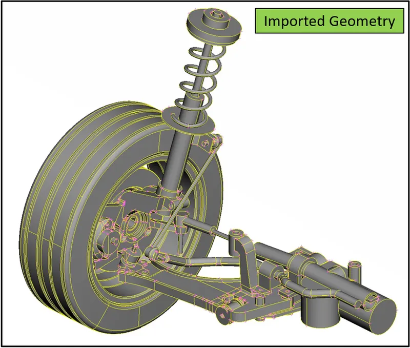
After importing the geometry in the ANSA user interface the user check for the geomtry check and founds the below geometrical error which is to be fixed before. But as we can see that there are huge number of parts available in the model it is very hard to identify the error properly so we first segregate each and every part and then clean the geometry one by one.
(**Note - Segregation of all the parts is explained below.)
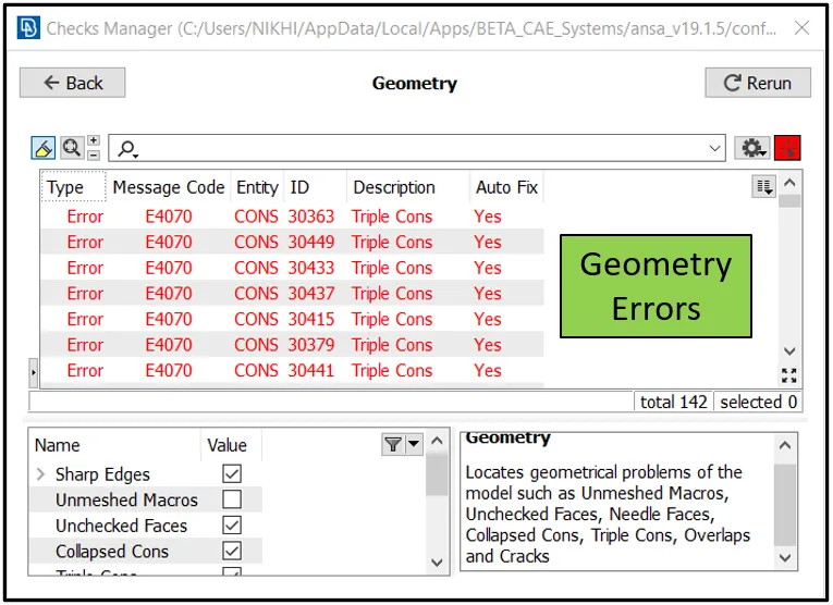
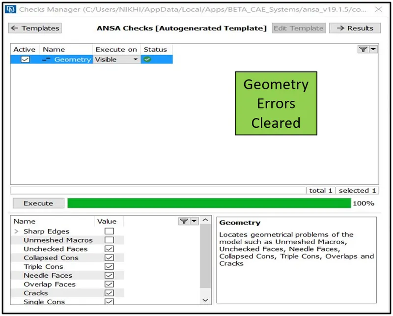
So one by one we segregate the part.
#Segregation of all parts under different property ID
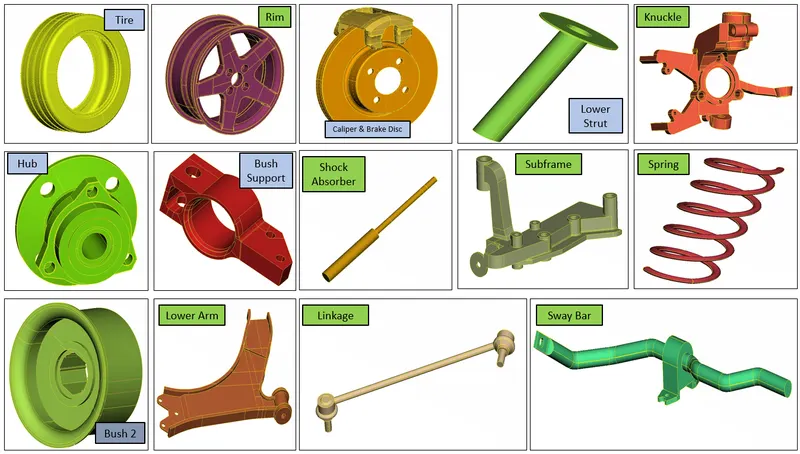
To segregate each single single part we use the tool bar avialable in the ANSA user interface named as INOT along with AND & NOT. Once the part is selected with the PID option next is we define the SET PID for each components. All the segregated componwents of the above assembly model is as shown below with proper nomenclature.
#Quality parameter and Mesh parameter setup
Once after segregating all the components of the model the user define the quality and the mesh parameters so that required mesh element lenght can be obtained during the meshing operation.
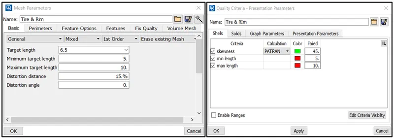
1. Set the quality and mesh parameter as given for Tire and Rim.
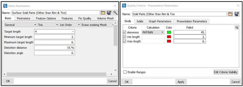
2. Set the quality and mesh parameter as given for all other components other than tire and rim (only solid parts).
3. Set the quality parameter for component with uniform thickness less than 5mm.
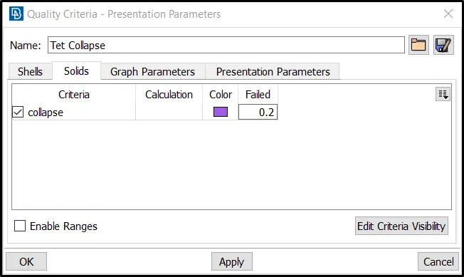
4. Set the solid quality parameter for the Tetra element collapse value 0.2.
#Defeaturing of the construction lines in the parts.
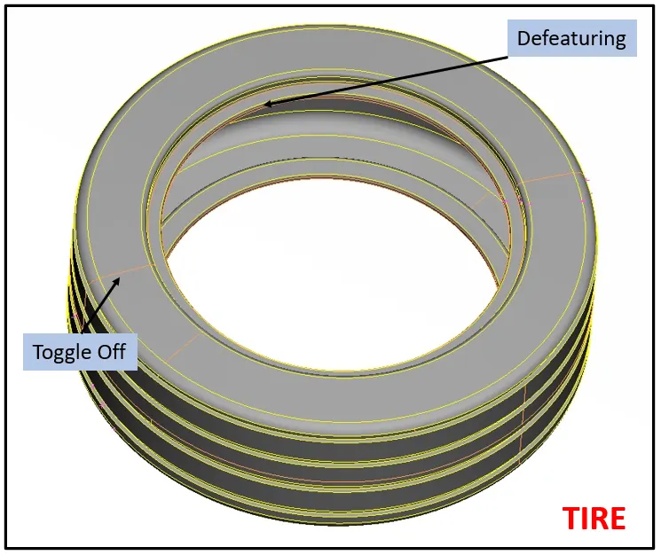
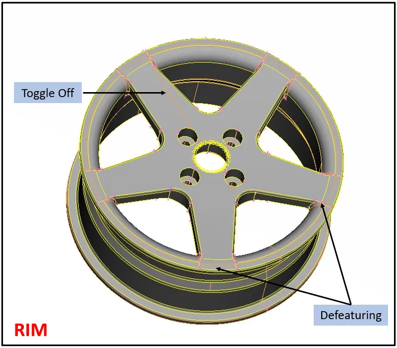
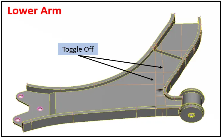
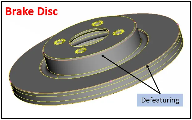
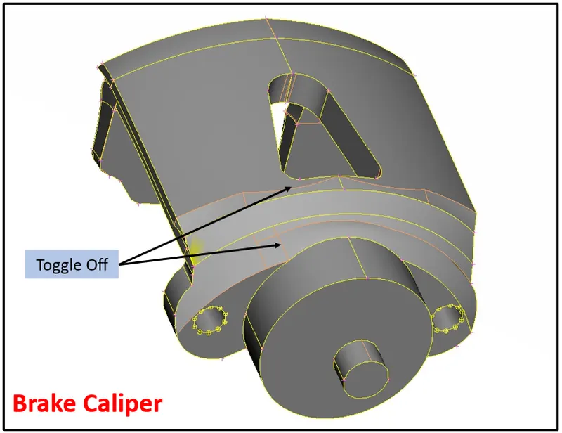
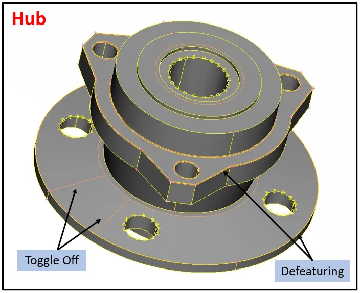
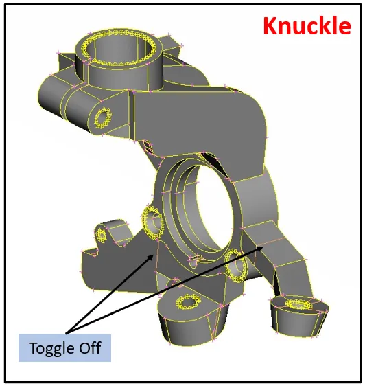
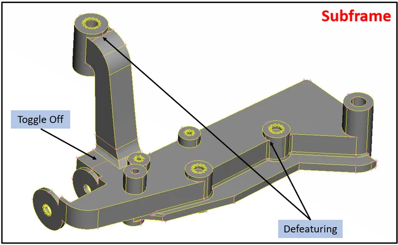
For capturing the component properly we need to defeature and toggle off few construction lines and check geometry before going for meshing the component. Few of the areas are shown below:
1. Tire & Rim
2. Lower Arm & Brake Disc
3. Brake Caliper & Hub
4. Knuckle & Subframe
#Midsurface Extraction of the componeents with non uniform thickess below 5 mm
All the components with less than 5mm thickness are midsurface using the offset option. This mid-surfaced compoenents will be further meshed using the shell elements properties as explained above.
#Shell Meshing of all the components and Mesh correction
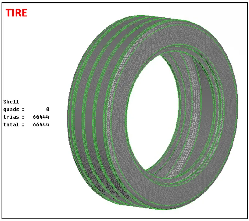
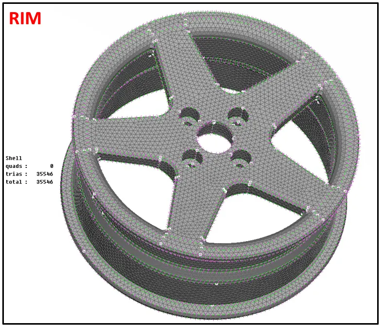
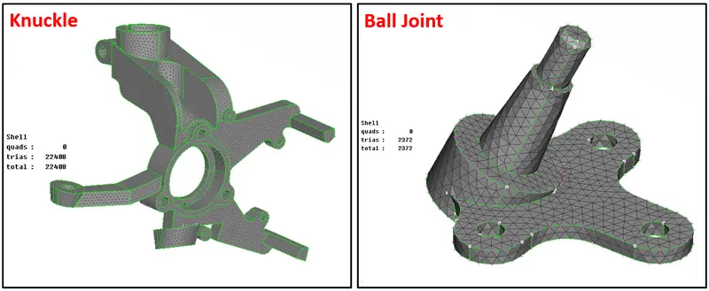
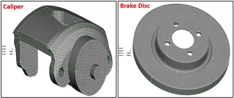
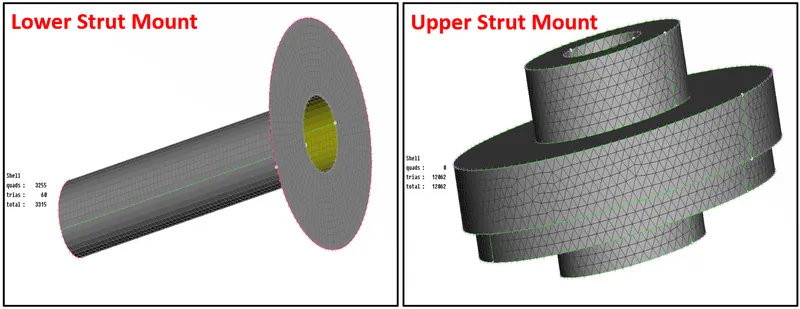
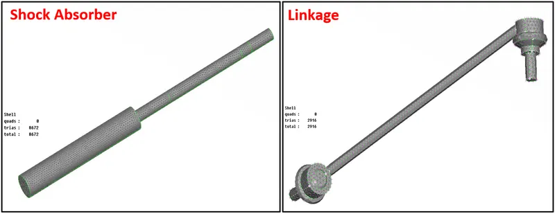
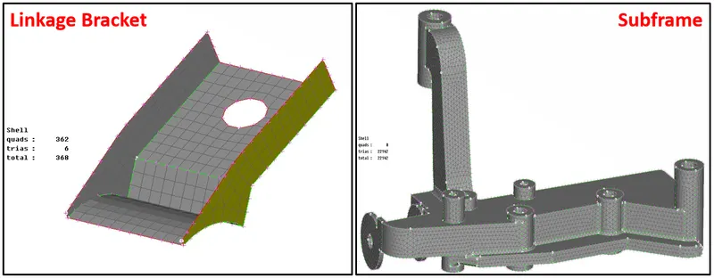
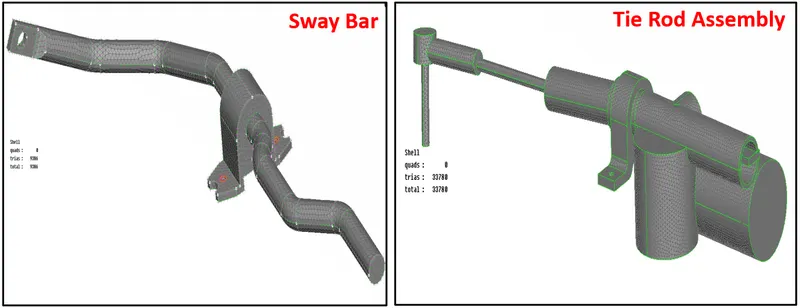
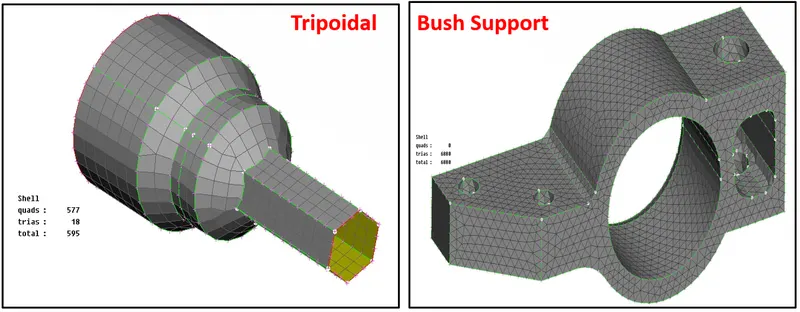
To perfoem shell meshing on the components the user first define the lenght of the perimeter and macross in the mesh module under the perimeter tab. Once the length is defined the user start meshing the components once by one using the shell mesh option. For performing the shell meshing the user use spot mesh and best mesh option under the mesh generation panel and along with these various shell mesh panel tool to repair the failed element and obtain good mesh flow. Below are some representaton of the components with shell mesh with total number of tria element counts on the left side.
1. TIRE & RIM
2. Knuckle & Ball Joint
3. Brake Caliper & Brake Disc
4. Strut Mounts
5. Shock Absorber & Linkage
6. Linkage Bracket & Subframe
7. Sway Bar & Tie Rod Assembly
8. Tripoidal Mid & Bush Support
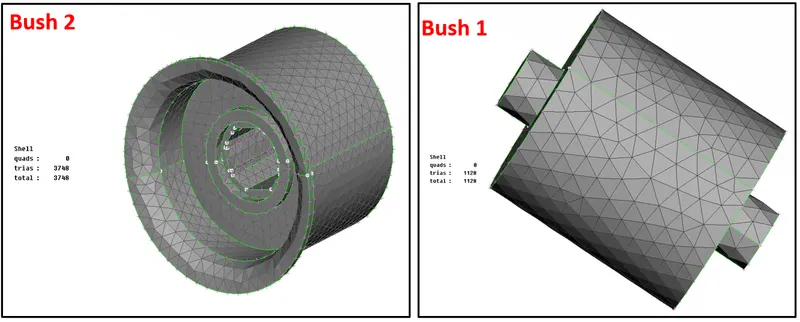
9. Bushes
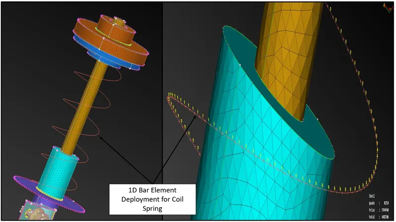
10. Bar element (1D reperesentation) deployment for Coil Spring
To deploy the 1D representation for the coil spring first the user convert the spring into the middle curve using curve middle tool. After these swith to Nastran module. Select element type as CBAR and using the curve deplot the bar element. While deploying 1D representation of the coil spring ANSA will ask for the parameter of spring like diameter of the spring to define the area and also thckness of the element which is must to represent the spring properly.
#Volume definition and 3D mesh generation for other than mid-surfaced components
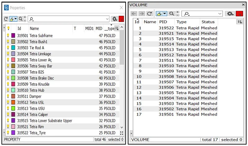
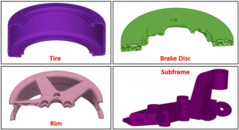
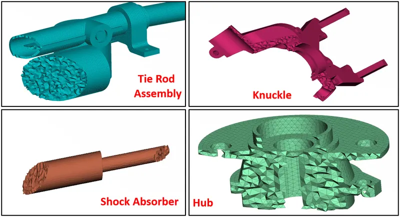
The next step we need to do is define them volume and generated Tetra elements through the volume but before defining them on the list we need to make sure the part is properly meshed and closed. Also, the part should not contain any overlapping surface. Define them one by one and set different PID type Solid as shown below figure. I have used Rapid Tetra mesh algorithm to auto-generate the Tetra element inside the volume.
#Implementation of connections at required area & defing the thikness of the shell & bar element using parameter representation
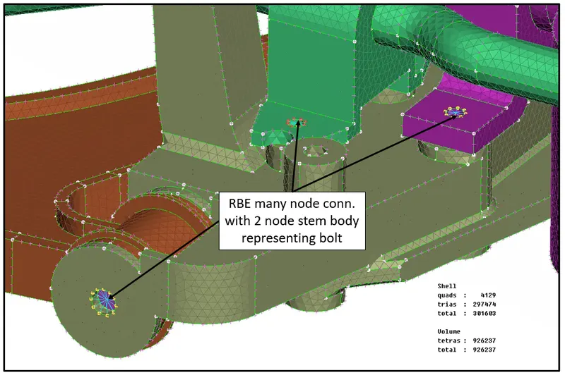
There are specific areas that need connections representing bolt, weld, and rigid connections. In the below figures attached it can be easily seen where and why these connections required.
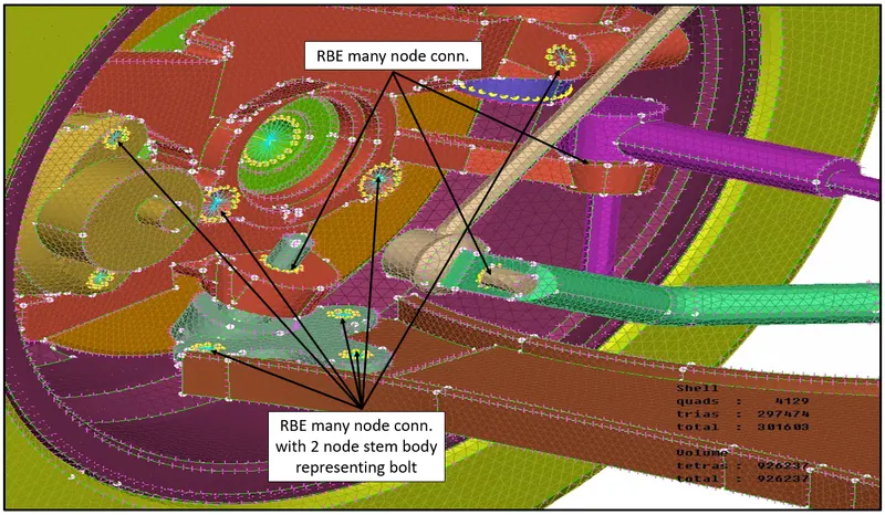
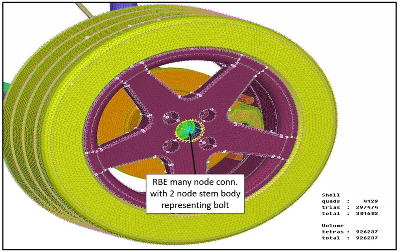
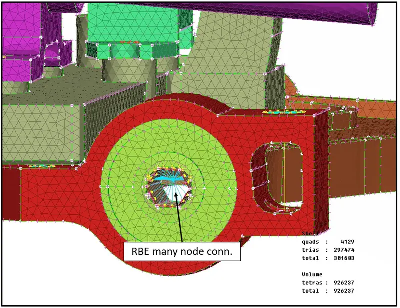
As there is no allignment between the rim, brake disc and hub, deployment of bolt connection is not possible for this model. Alternate way to deploy the connection is many node rbe2 with stem body representing bolt connection between hub and rib is deployed as shown below.
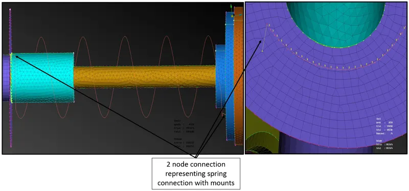
As the coil spring is represented as bar element it has to be connected with the lower and upper strut mount. To deploy connection between them user deployed 2 node rbe element as shown below.
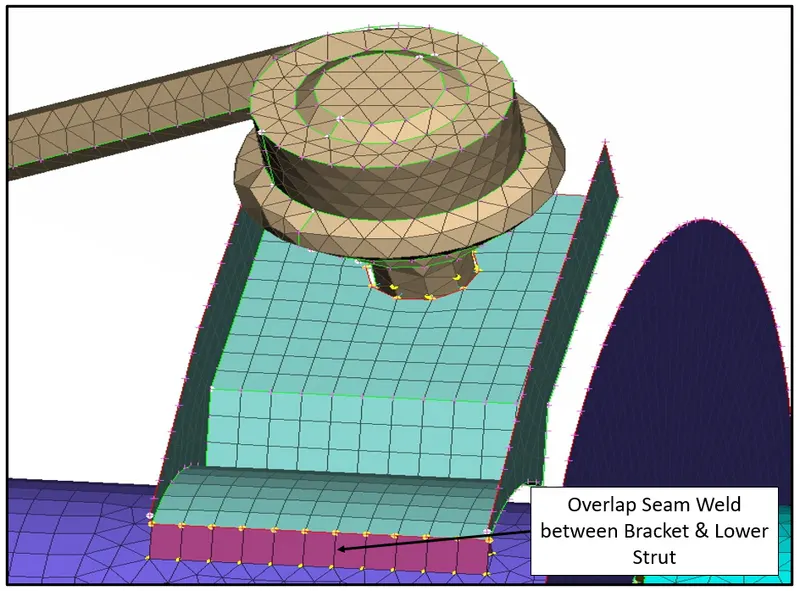
Overlap Shell Seam Weld Connection between Mounting bracket and Lower Strut Mount
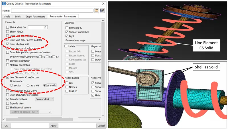
Assinging shell thickness for the midsurface and solid line for bar element
To assign the thickness for the shell elements and bar element the user switch on the quality criteria window and under the presentation parameter tab check the required option as shown below.
FINAL RESULT :-
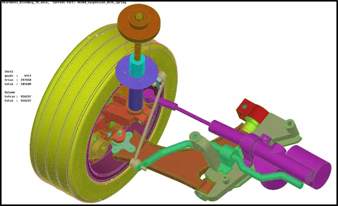
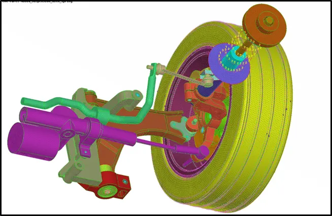
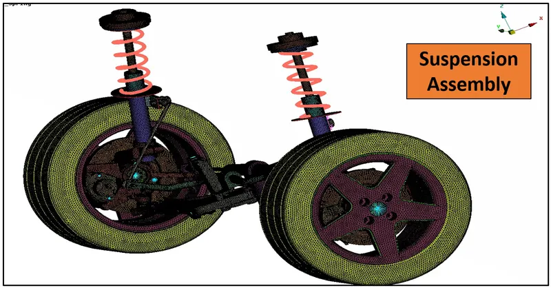
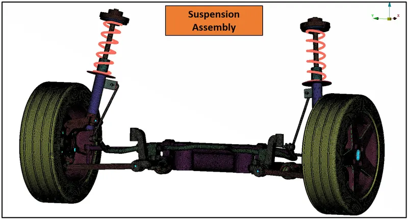
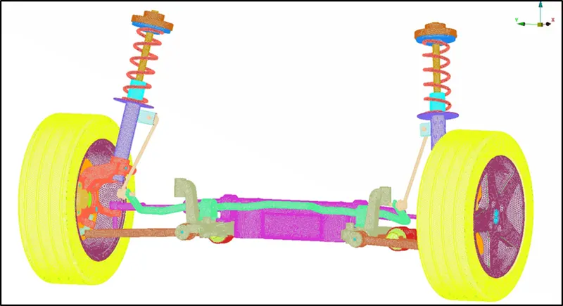
So finally we have completed the meshing process, connection and get the final model as shown below,
Final Model Half without Symmetry
Final Model Full View with Symmetry
CONCLUSION:
All the components of a suspension system are captured quite decently with solid elements(Tetra) and shell element (Quad+Tria) as per the quality requirements. The sufficiently required connections are given with the RB2 cluster and two-node RB2. There is a total to 870020 tetra element under the volume meshing (3D) free from any Tetra collapse. The curved areas were mainly captured with the ortho Tria element during shell meshing on solid objects which helped to capture the feature correctly. The meshed final model has a smooth surface free from any dip or kinks and can be considered further processing.
#LEARNING OUTCOME:
1. Geometry check and cleanup.
2. 1D, 2D(shell), and 3D(solid) meshing.
3. Implementation of connections.
4. Car suspension system components and their purpose.