Project - 2 - Meshing on the suspension Assembly
Project 2
Aim- Meshing on Suspension assembly.
Google Drive Link of assignment - https://drive.google.com/file/d/1IjWXpeKywiRIKSBcfZyln2C-a4AhvVS6/view?usp=share_link
Procedure-
Step 1- Imported the Geometry
Step 2- Improved cons resolution from mesh module- perimeter- length – 1.
Step 3- Set orientation from Topo module -Faces- orient
Step 4 – Checked for connectivity between surfaces from topo module – faces-topo.
Step 5- Geometry checks – tools – checks – geometry- fix.
Step 6- Checked for number of properties – ctrl+P (shown in fig 1)
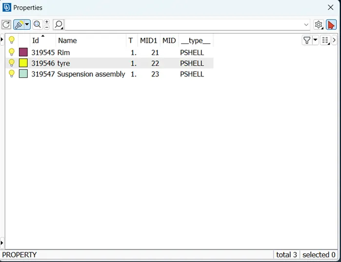
Fig 1- Property card.
Step 7-The Project is a complete assembly of different part. To make things simpler, we separated the complete assembly into different Parts. From Topo module-Faces-PID-PID selection-MMB and separated the complete assembly.
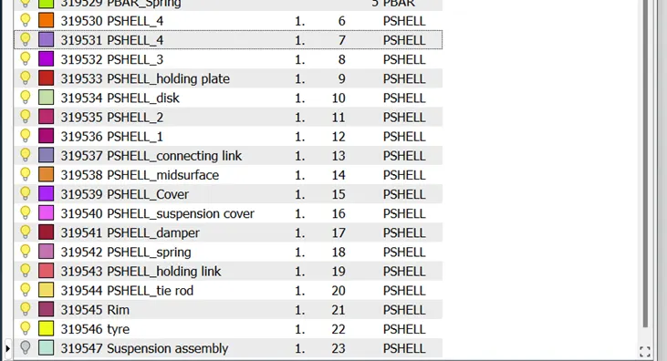
Fig 2- Different PIDs set for simplification
Step 8- Worked on one property by turning off the other cards.
Step 9- Working on Spring of suspension.
Step I – Spring can be modelled as 1 D element as Cbar or C beam element. To create represent the spring we first created the curve at the middle of the spring part. From Topo modules – Curves -Middle- Selecting the cons -MMB.
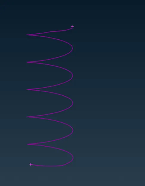
Fig 3 – middle curve of Spring
Step II – The Curve is assigned the CBar element from Nastran Deck- Elements -C Bar -Change nodes to curve (seq)- selected the curve- element length ~ 5 – MMB – New Property help window appears -RMB – new – Area (A) -Shift + ? – Diameter (D) 10 – ok- Double click on new created property - close the tab
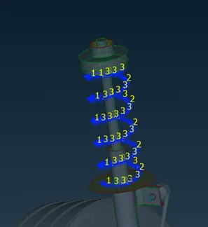
Fig 4 – Cbar element on the middle curve.
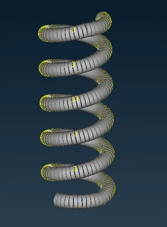
Fig 5 -Cbar elements to represent the spring.
Step 10 – 2D meshing on Component and mid surface on specific component, the mid surface is extracted using the casting algorithm.
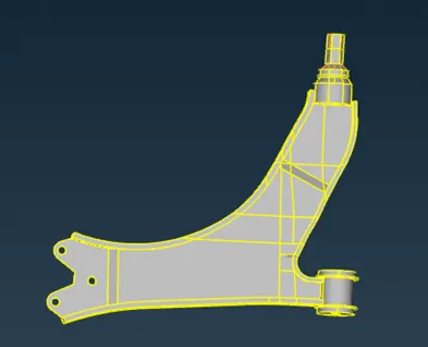
Fig 6 – Component for 2D meshing.
Step I- Fixed the quality criteria as per the assignment, from utility menu- quality criteria fixed the quality-ok.
Step II- The mid surface and mesh both are automatically created form, Topo module- faces- Mid surface- casting- minimum thickness-2-Target element length – 4- ok, mid surface and mesh will be generated.
Step III – Fixed the failed elements using Smooth, Reconstruct, improve commands etc. and followed the same process for other components.
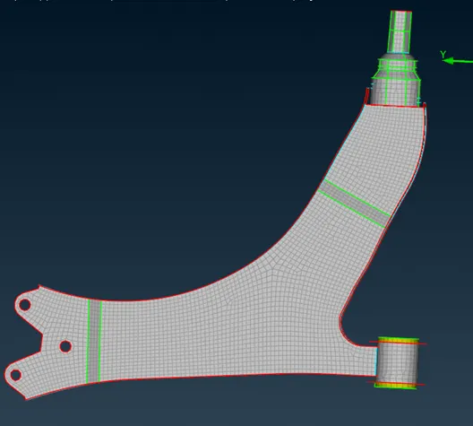
Fig 7 -Complete component 2D meshing
Step 10 – 3D (Solid) meshing of the component
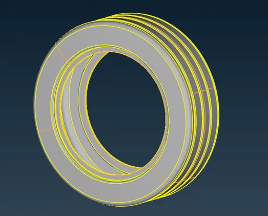
Fig 8- Component for Solid meshing
Step I- Measured the distance between to cons and suppressed the two cons to avoid failure of elements as per quality criteria.
Step II – Preformed the Shell meshing by considering the Tria mesh.
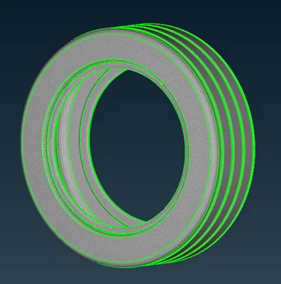
Fig 9 – Shell meshing
Step III – Checking for penetration, From Tools- Checks- Penetrations- Intersections.
Step IV- Converted shell mesh to volume mesh, from Volume mesh module-Volume- define- allotted the volume Property Card.
Step V- Performed volume mesh form Volume mesh module- unstructured mesh- Tetra Rapid- select the part.
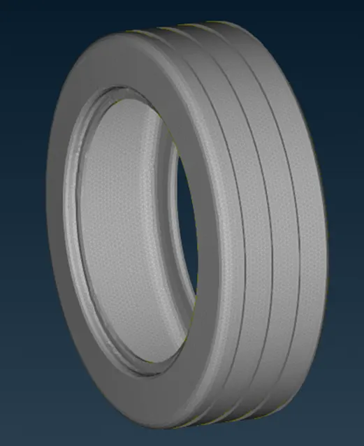
Fig 10 -Solid mesh.
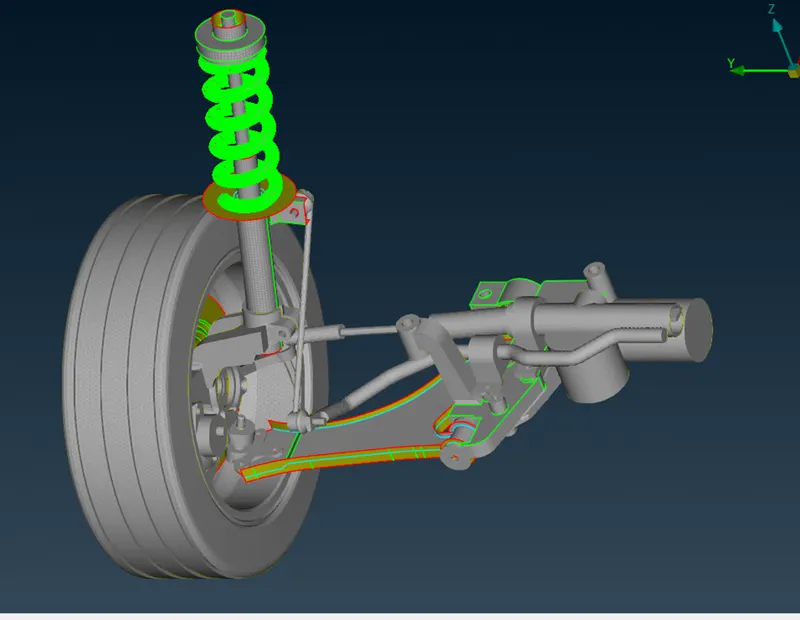
Fig 11 – Meshing of complete assembly,3D,2D,1D
Step 11 -Connections.
- Bolt Connection.
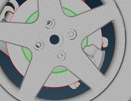
Fig 12 – Location of bolt
Step I – The bolt is connected between two holes we first create the master node at the center of hole form, Nastran – Elements-RBE2-multiple- selected the loop- MMB- next- Next – Finish, Similar process for remaining parallel hole.
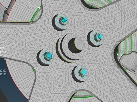
Fig 13- Master element at center of hole
Step II- We connected the two master nodes by adding one more element and restricting to 1 DOF from, Nastran-Elements-RRE2- Two nodes- Selected the two master nodes- MMB- Changed name to bolt 1- CM to 123456-OK.
Step III – Applied the same process for different bolt location.
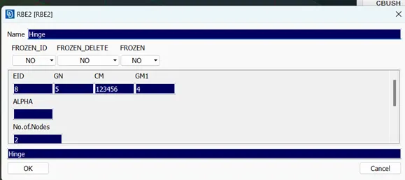
Fig 14- RBE 2 window
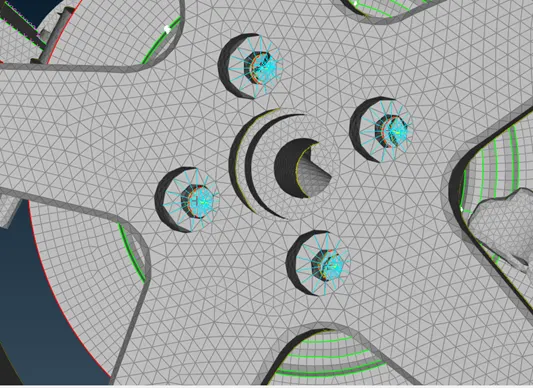
Fig 13 – Bolt connection
Step IV – Applied the same process for the bolt location and hinge location. Except for hinge CM – 12345 to remove the rotation about Z- axis.
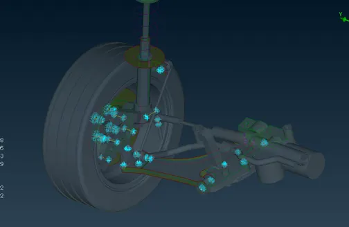
Fig 14- Bolt and hinge connection
- Weld Connection
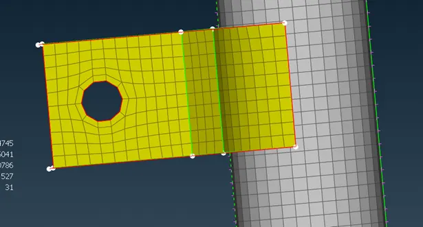
Fig 15- location for weld connection
Steps I- as it is a line connection, We first need to create the curve , form Mesh module- Perimeter-Feat to curve- and select the elements-MMB and created the curve.
Step II- The curve is converted to Seam line from, Assembly menu- Convert-Curve -Select curve- MMB-Connection type -seam Line.
Step III- connected the curve to the PID, from Assembly menu- Connection Manager- select Spot Line- MMB- connection manager window appears.
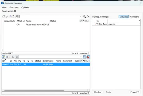
Fig 16- Connection manager window.
Step IV – Assign the PIDs by P1-LMB- Manage-RMB-Shift +F1- select the PID -MMB -Enter. and same process to assign other PIDs.
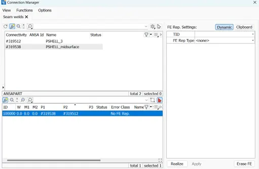
Fig 17- connection manager window after assigning PIDs.
Step V – Assigning the FE rep type-overlap Shell, Search Distance – 50,
Step VI – Assigned the weld Property from shell attributes-weld prop -Shift +?- New -assigning the property – ok - select the new weld property ID created-Apply -Realise.
Step VII -Applied the same process at different location.
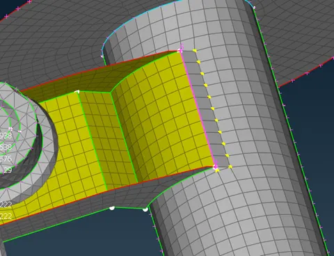
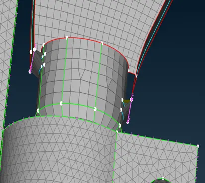
Fig 18- Weld Connection
Step 12 – Mirror the complete assembly
The complete assembly is symmetric. The assembly is mirror from, Utility menu- Transform-copy-Select the entire assembly with the help of box select-MMB-Symmetry- change from default plant to e point plate – Selected the 3 points of the most extreme plane -apply-ok-Finish.
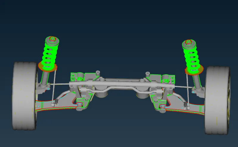
Fig 19-Complete Assembly
Conclusion
- Learned about the Suspension assembly of rear wheel.
- we Learned about the 1D ,2D ,3D meshing, extracting mid surface using Casting and applications of the same.
- We learned about the different types of connection.