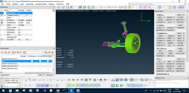
Project - 2 - Meshing on the suspension Assembly
PROJECT-2
AIM:
For the given assembly, geometrical errors to be checked and meshed as per the given quality criteria parameters. Then necessary connections to be given and thickness should be assigned.
MESHING THE COMPONENTS OTHER THAN TYRE AND RIM
PROCEDURE:
STEP 1: IMPORTING
Opening ANSA and importing the given assembly by FILE-OPEN-SELECTING THE FILE.
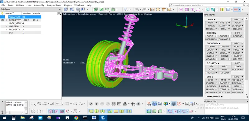
STEP 2: TOPO and ORIENT
Improving the assembly topology by TOPO DECK-FACES-TOPO.
Improving the assembly orientation by TOPO DECK-FACES-ORIENT.
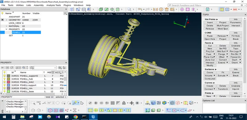
STEP 3: ASSIGNING PID
As the assembly contains several parts so each parts are separately isolated and assigned a separate PID by TOPO DECK-FACES-SET PID option.
STEP 4: GEOMETRY CHECKS
Each PID is separately isolated using INOT option and geometry checks to be done using TOOLS-CHECKS-GEOMETRY-EXECUTE.

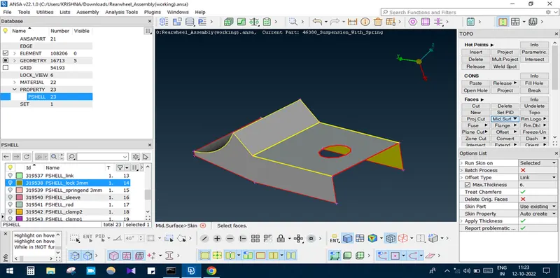
STEP 6: MID SURFACE GENERATION.
Each PID is separately isolated using INOT option and If the thickness is less than 5mm and have uniform thickness means mid surface to be generated by TOPO DECK-FACES-MID SURFACE-SKIN option and TOPO DECK-FACES-OFFSET option.
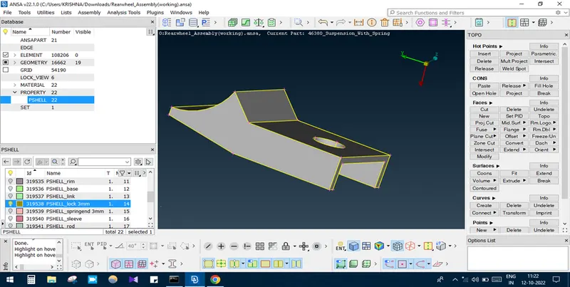
STEP 7: SHELL MESHING
- Some component's mid surfaces were generated for which shell meshing was performed after GEOMETRY CHECKS and GEOMETRY CLEANUP.
- Quality criteria and mesh parameters are applied as per the instructions given.
- Then perimeter element size is given by CLASSIC MESH-PERIMETER-LENGTH option.
- Meshing is done by CLASSIC MESH DECK-MESH GENERATION-BEST option.
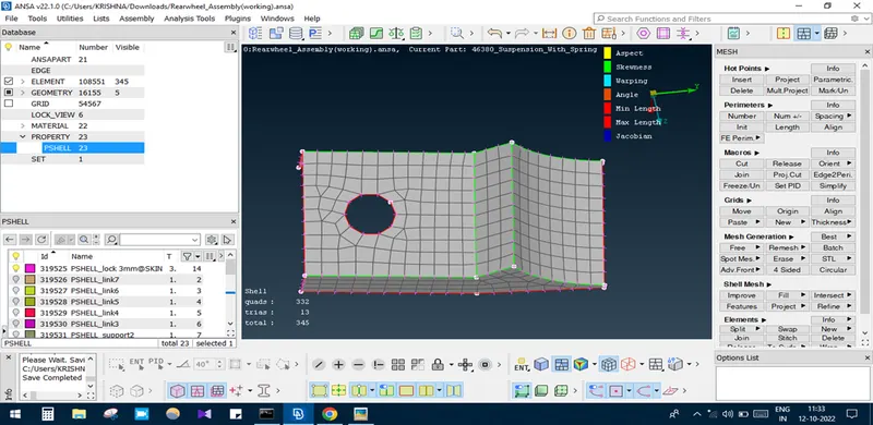
STEP 8: IMPROVING THE QUALITY OF MESH
As the generated mesh flow/element is not as much as good so its quality must be improved by CLASSIC MESH DECK-SHELL MESH-RECONSTRUCTION and SMOOTH option.
Trias at the free edge and other quality defect are eliminated by CLASSIC MESH DECK-ELEMENTS-SPLIT and SWAP option.
STEP 9: ASSIGNING THICKNESS TO SHELL ELEMENTS.
In order to convert shell elements into solid elements we are assigning required thickness value to respective shell elements PID and in quality criteria parameter
MESHING-TYRE, RIM AND OTHER COMPONENTS
As per the instruction given the tyre and rim are volume meshed.
STEP 1: ISOLATING, TOPOLOGY, ORIENTATION
Initially the tyre geometry is isolated using INOT option. Topology and orientation issues has to be sorted out.
STEP 2: GEOMETRY CHECKS
Error in the geometry has to be checked by TOOLS-CHECKS-GEOMETRY-EXECUTE option.
STEP 3: MESHING
- Mesh parameter and quality criteria are applied as per the given instructions.
- Proper element length is assigned by CLASSIC MESCH DECK-PERIMETER-LENGTH Option.
- Meshing is performed by CLASSIC MESH DECK-MESH GENERATION-BEST option.
- Quality of the mesh is improved using RECONSTRUCTION and SMOOTH option.
STEP 4: DEFINING VOLUME TO SHELL ELEMENTS
- To convert the shell elements to volume elements define option is used by VOLUME MESH DECK-VOLUME-DEFINE option.
- Assigning the mesh type as TETRA FEM and by selecting the REMESH option, the volume meshing is done.
- Similarly, the same procedure is applied to rim components and volume meshing was performed.
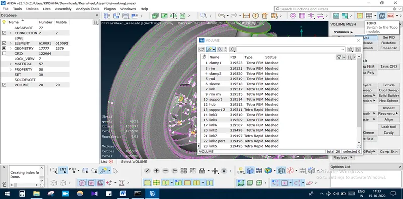
STEP 5: QUALITY IMPROVEMENT
In volume meshing, quality failure is checked for TET COLLAPSE. In case of any failure, it has to be solved by using CLASSIC MESH-GRID-MV FREE option.
STEP 6: MESHING OTHER COMPONENTS
The same procedure is repeated for other components but checked with different quality criteria values which are mentioned on the instructions.
CONNECTIONS
STEP 1: SPRING AS 1D BAR ELEMENT
- This type of connection is applied to the spring component in the suspension system.
- Initially the spring component is isolated using INOT option.
- Middle curve is created by using TOPO DECK-CURVE-MIDDLE option.
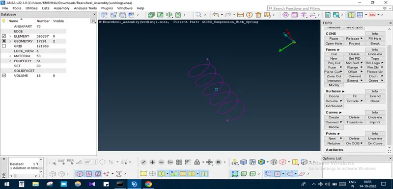
- COG point to be created by using TOPO DECK-POINTS-ON COG option.
- Going to NASTRON DECK-ELEMENTS-CBAR option is selected.
- In elements definition parameter dialog box, orientation with node option is selected and curve(box) option also selected.
- Then the curve is selected and middle clicked.
- Selecting the COG point as orientation node
- Then the elements length has to be specified and after doing middle click PID has to be assigned by RIGHT CLICK-NEW option.
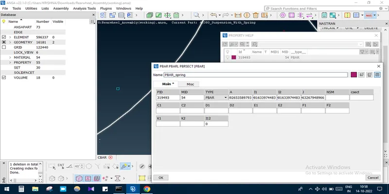
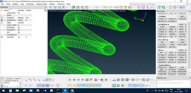
- After giving necessary values, clicking OK and PID will be assigned and 1D bar element is created
- In quality parameter option, in the presentation parameter-line cross-section to be checked and AS SOLID option to be checked.
STEP 2: SEAM WELD CONNECTION
- First the two components are isolated using INOT option.
- A curve is created using TOPO DECK-CURVE-CONS2CURVE option.
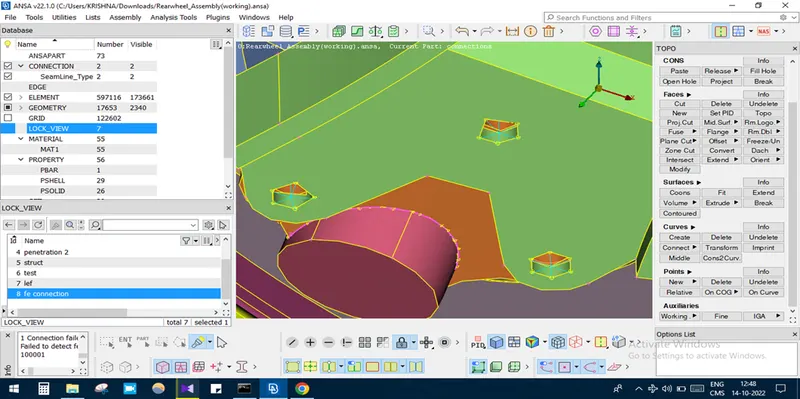
- Selecting CONVERT option-CURVE-SELECTING THE CURVE-SEAM LINE-OK.
- Selecting the connection manager-selecting the curve and middle clicking-selecting P1 and P2.
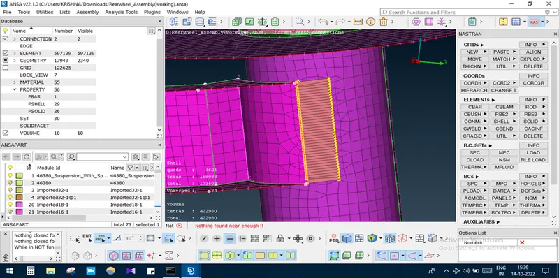
- In the FE rep type as OVERLAP SHELL and assigning the proper SEARCH DISTANCE-APPLY-REALIZE.
- The seam weld will be realized.
STEP 3: RBE2 connection.
- This type of connection is done to represent the bolt and some rigid connection as well.
- Initially the required components are isolated.
- Going to NASTRON DECK-RBE2-MANY NODE-SELECTING THE NODE-OK.
- The created RBE2 connections are separately stored in an ANSA part by using the MODEL BROWSER option.
- RBE2 connections are applied between tyre and rim, two bolt mating components (using RBE2-2 node option), spring endpoints.
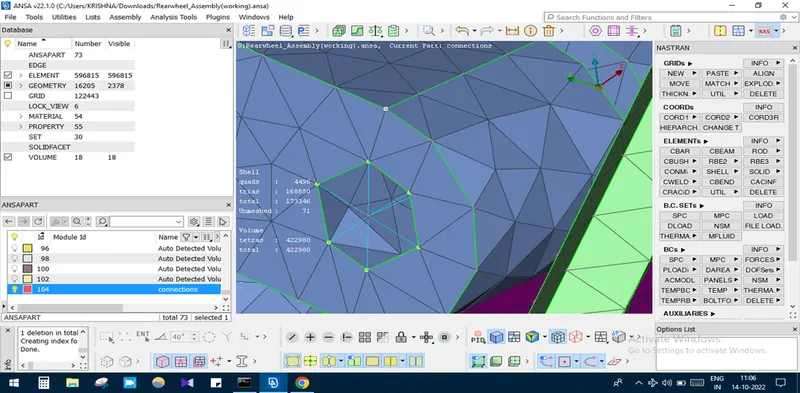
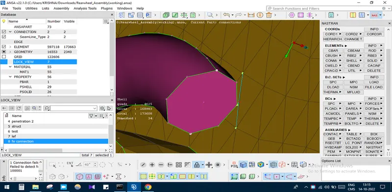
FE model without enabling the thickness
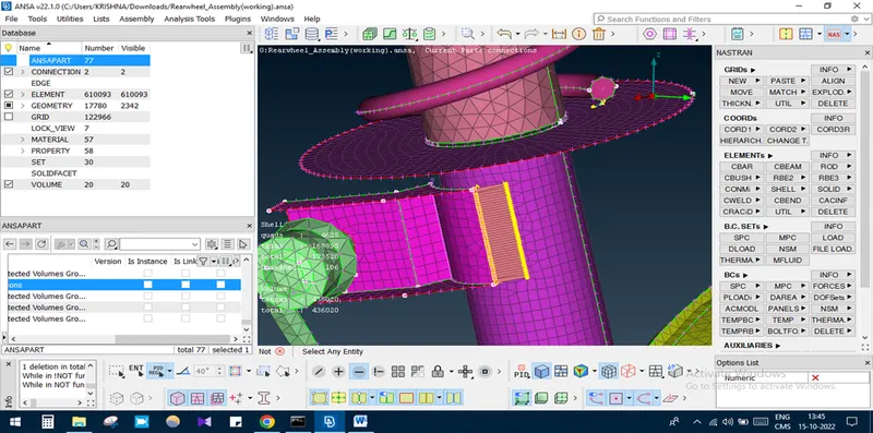
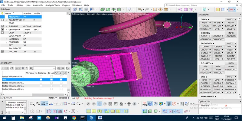
FE model with enabling the thickness
LEARNING OUTCOMES:
From the given assembly, I have learned how to do assign proper PID for each and every component, mid surfacing, shell meshing, volume meshing and connections and its applications.
Conclusion:
Thus the given assembly was properly meshed with the given quality criteria parameter and applied effective connection in desired locations.
FINAL OUTCOME: