Project - 2 - Meshing on the suspension Assembly
Aim :-
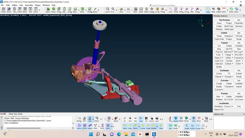
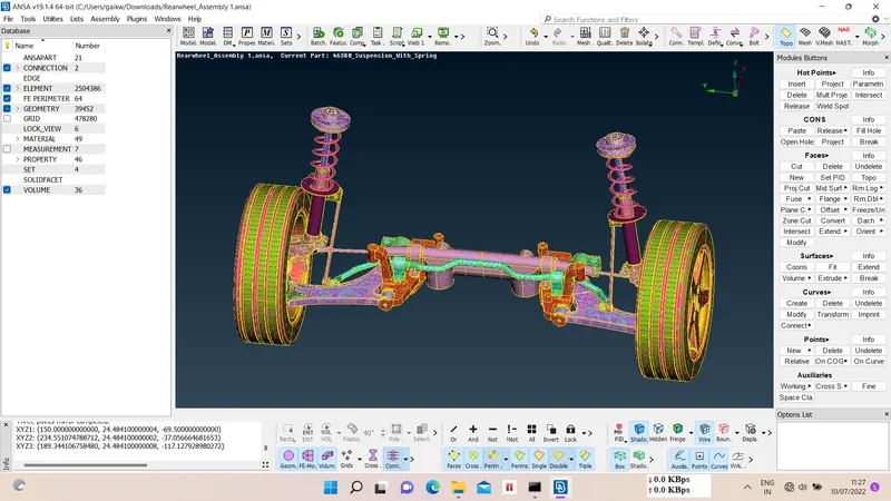
For the given assembly, check for the geometrical errors and mesh with the given element Quality criteria. After meshing the component the thickness has to be assigned for mid surfaces. Use tetra elements to model non-uniform thickness components. Also use Appropriate connections to connect the component as suggested in the Project-2 video (Use PBAR elements to model suspension spring). At last perform Symmetry command to reflect the half finished model to the other side.
Write a detailed report on your meshing process and also mention which method you used to extract the mid-surface along with the reason.
Ans :-
1) Geometry Import -
First import the model using file - open option and give topo to geometry.
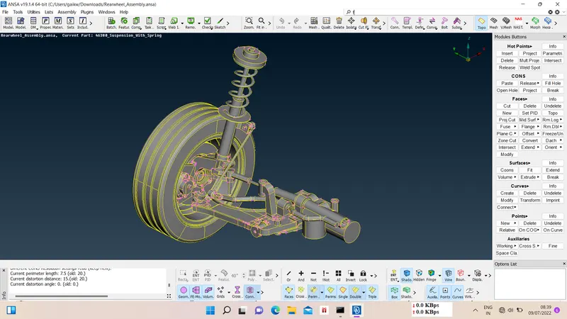
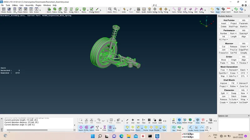
2) Geometry check and Topology cleanup -
We have to check the gometry of model for geometrical errors, for that check - geometry. Ideally model should have zero geometry errors, so to fix the errors we use autofix option and some errors we have to fix manually.
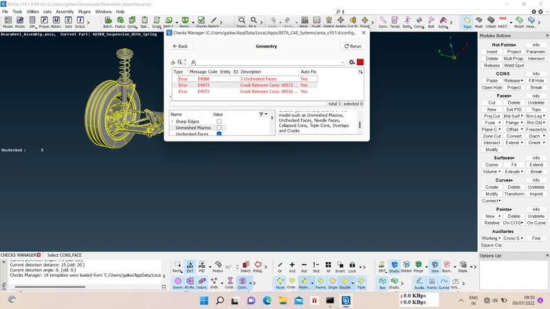
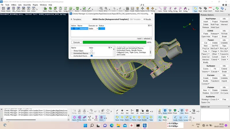
3) Measurements and Property assigning -
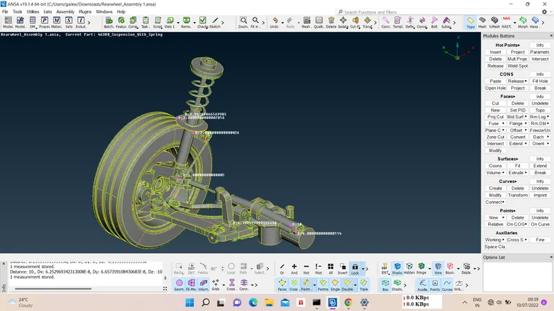
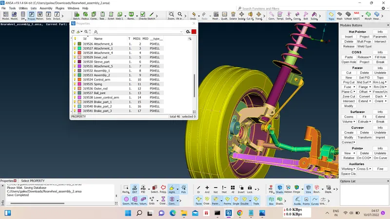
We have to measure thickness at different area of model for further meshing scenario.After the geometry cleanup we need set new PID for model, we assign new PId using set PID option. We can see new PID in properties option of list PID.
4) Midsurfacing -
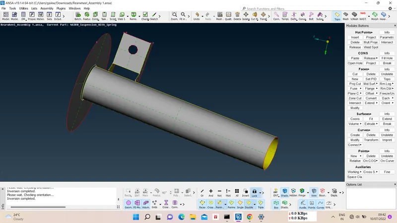
For parts less than 5mm thickness we have to take midsurface for meshing, for that Offset - faces - ok.
5) Quality criteria and Mesh parameters -
Now we have to apply given quality criteria and mesh parameters for different parts as below
i) Quality Criteria for Surface Meshing of Tyre and Rim (Element type: Tria) :
|
S.No |
Quality Criteria |
Value |
|
1 |
Target/Average length |
6.5 |
|
2 |
Minimum Length |
5 |
|
3 |
Maximum Length |
10 |
|
4 |
Skewness |
45 |
ii) Quality criteria for Surface Meshing of Non Uniform thickness components other than Tyre and Rim (Element type: Tria) :
|
S.No |
Quality Criteria |
Value |
|
1 |
Target/Average length |
4 |
|
2 |
Minimum Length |
2 |
|
3 |
Maximum Length |
6 |
|
4 |
Skewness |
45 |
iii) Quality Criteria for Volume meshing of all Non Uniform thickness components (Element type: Tetra Elements):
|
S.No |
Quality Criteria |
Value |
|
1 |
Tet-collapse |
0.2 |
iv) Quality criteria for Mid surfacing of Uniform thickness part which has thickness less than 5 mm (Element type: Mixed elements) :
|
S.No |
Quality Criteria |
Value |
|
1 |
Target/Average length |
4 |
|
2 |
Minimum Length |
2 |
|
3 |
Maximum Length |
6 |
|
4 |
Aspect |
3 |
|
5 |
Warpage |
15 |
|
6 |
Skewness |
45 |
|
7 |
Jacobian |
0.7 |
|
8 |
Minimum Quad Angle |
45 |
|
9 |
Maximum Quad Angle |
135 |
|
10 |
Minimum Tria Angle |
30 |
|
11 |
Maximum Tria Angle |
120 |
6) Meshing -
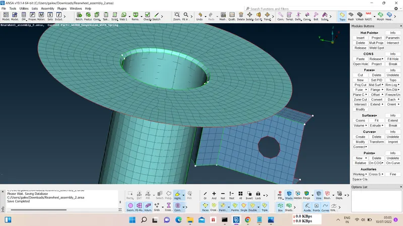
We have to do two types of meshing in this model 2D meshing and volume meshing according to thickness of the parts.
for 2D meshing - shell mesh - mesh generation - best - select part - ok.
for volume meshing - volume mesh - volumes - define - unstructured mesh - tetra rapid - select part - ok.
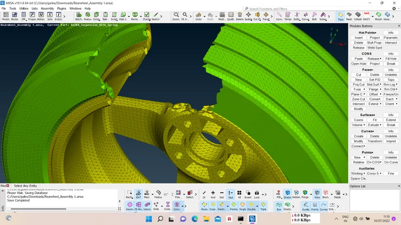
In volume meshing for planer surfaces we used mixed mesh type and for curve surfaces we use tetra mesh type.
Now we have to check elements for quality faillures by switching to hidden mode, if there are any
elements which are failing for quality then we have to fix it by reconstruct, smooth, improve, etc. options.
7) Connections -
As meshing is done now we have to define connections of parts at different location in NASTRAN Deck Module as below
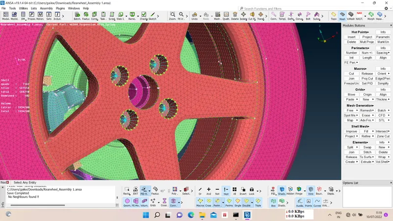
i) RBE2 connection - Elements - RBE2 - many nodes - select slave node -auto generate master node - part(set current part) - finish.
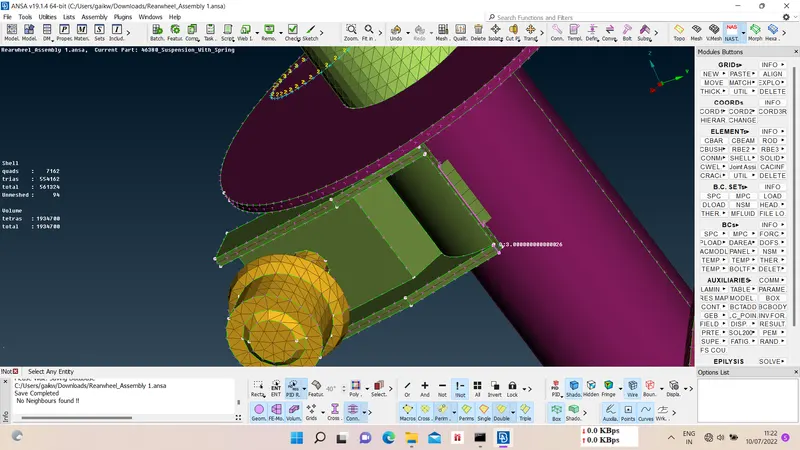
ii) Seamweld connection - curves - const2curve - create curve - assembly - select curve - convert to seamline connection - assembly - connections - select connection - confirm - connection manager - FE rep. type - choose parts - define search distance - parts number - base sheet - choose PId - root shells - double row - apply - realize.
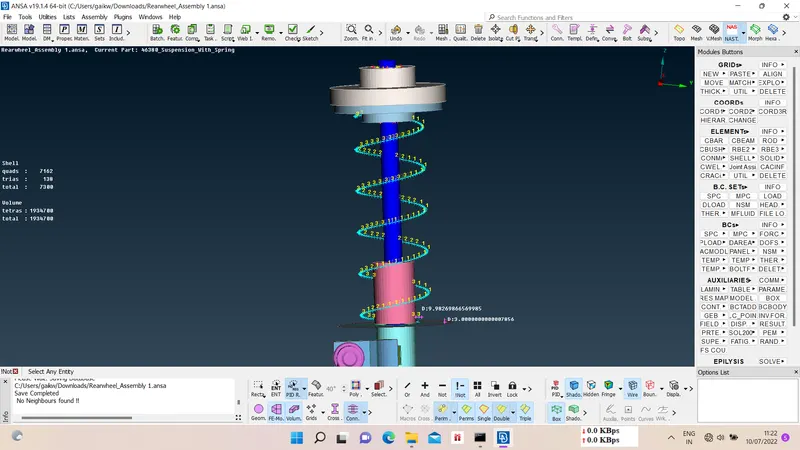
iii) Spring CBAR connection - create curves using curve middle - connect curves - elements - CBAR - select orientation - curve box - create point - select point - new PId - define radius - ok.
8) Symmetry -
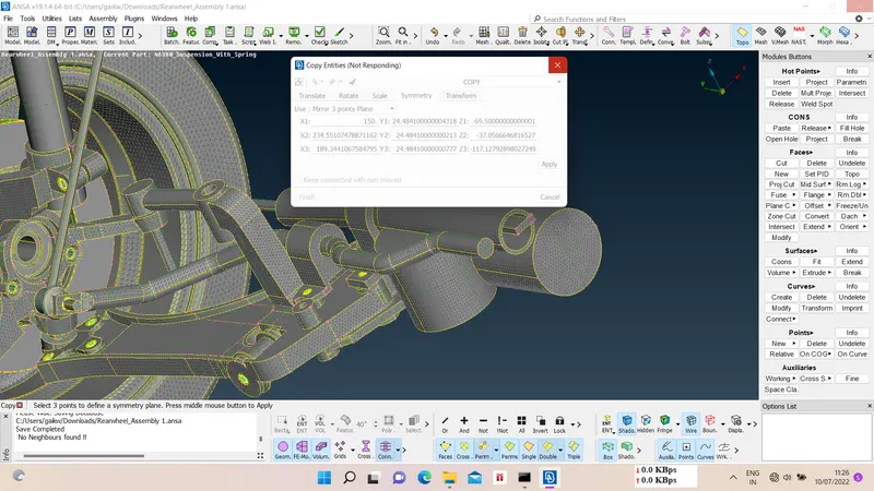
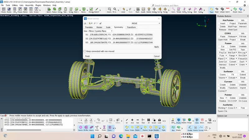
After meshing and defining connections we have to reflect the model by using symmetry option, for that
Utilitis - transform - copy - select entities - symmetry - give 3 coordinates - apply - finish.
Final Result :-
G-drive link :-
https://drive.google.com/file/d/1160gL5wOwFQJLnJ4rrXmPVoreUZWuWl_/view?usp=sharing