Meshing and Deploying Connections on the Rear suspension Assembly using ANSA
AIM :
To Check for the geometrical errors, take mid-surface and 2D mesh & Volume mesh(tetra mesh) with the given element Quality Criteria for the given Component and perform suitable connections.
OBJECTIVE :
For the given assembly, check for the geometrical errors and mesh with the given element Quality criteria. After meshing the component the thickness has to be assigned for mid surfaces. Use tetra elements to model non-uniform thickness components. Also, use Appropriate connections to connect the component (Use PBAR elements to model suspension spring). At last, perform the Symmetry command to reflect the half-finished model to the other side.
Quality Criteria for Surface Meshing of Tyre and Rim (Element type: Tria) :
|
S.No |
Quality Criteria |
Value |
|
1 |
Target/Average length |
6.5 |
|
2 |
Minimum Length |
5 |
|
3 |
Maximum Length |
10 |
|
4 |
Skewness |
45 |
Quality criteria for Surface Meshing of Non-Uniform thickness components other than Tyre and Rim (Element type: Tria) :
|
S.No |
Quality Criteria |
Value |
|
1 |
Target/Average length |
4 |
|
2 |
Minimum Length |
2 |
|
3 |
Maximum Length |
6 |
|
4 |
Skewness |
45 |
Quality Criteria for Volume meshing of all Non-Uniform thickness components (Element type: Tetra Elements):
|
S.No |
Quality Criteria |
Value |
|
1 |
Tet-collapse |
0.2 |
Quality criteria for Mid surfacing of Uniform thickness part which has thickness less than 5 mm (Element type: Mixed elements) :
|
S.No |
Quality Criteria |
Value |
|
1 |
Target/Average length |
4 |
|
2 |
Minimum Length |
2 |
|
3 |
Maximum Length |
6 |
|
4 |
Aspect |
3 |
|
5 |
Warpage |
15 |
|
6 |
Skewness |
45 |
|
7 |
Jacobian |
0.7 |
|
8 |
Minimum Quad Angle |
45 |
|
9 |
Maximum Quad Angle |
135 |
|
10 |
Minimum Tria Angle |
30 |
|
11 |
Maximum Tria Angle |
120 |
THEORY :
Suspension :
The suspension is the system of tires, tire air, springs, shock absorbers, and linkages that connects a vehicle to its wheels and allows relative motion between the two. Suspension systems must support both road holding/handling and ride quality, which is at odds with each other. The tuning of suspensions involves finding the right compromise. It is important for the suspension to keep the road wheel in contact with the road surface as much as possible because all the road or ground forces acting on the vehicle do so through the contact patches of the tires. The suspension also protects the vehicle itself and any cargo or luggage from damage and wear. The design of the front and rear suspension of a car may be different.
Difference between Rear Suspension and Front Suspension :
Any four-wheel-drive (4WD/AWD) vehicle needs suspension for both the front wheels and rear wheels, but in two-wheel-drive vehicles, there can be a very different configuration. For front-wheel-drive cars, the rear suspension has few constraints, and a variety of beam axles and independent suspensions are used. For rear-wheel-drive cars, the rear suspension has many constraints, and the development of the superior, but more expensive independent suspension layout has been difficult. Four-wheek drive often has suspensions that are similar for both the front and rear wheels.
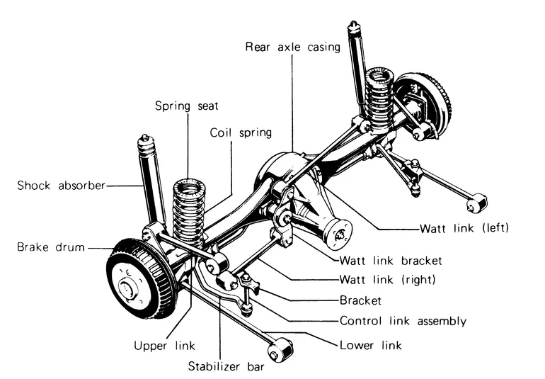
Fig: Rear Suspension Assembly
PROCEDURE :
A. Importing a Model & Geometry Cleanup :
1. Import the given model by using the File-->open option.
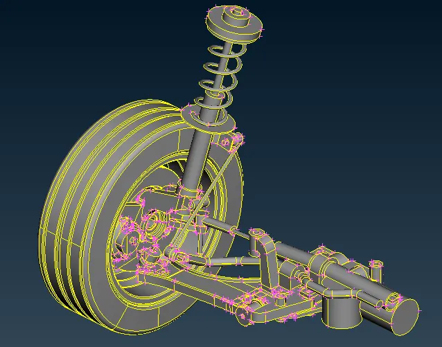
Fig: Rear Suspension Model
2. Go to Topo-->Faces-->Topo option and select all CONS and Click ok to stitch all CONS with each other.
3. Go to Tool-->Checks-->Geometry for Geometry Clean up.
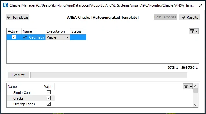
Fig: Checks Manager Window
4. In the above Checks Manager window click Execute to check any error occurred in the Model and fix the Error and Cleanup the Geometry.
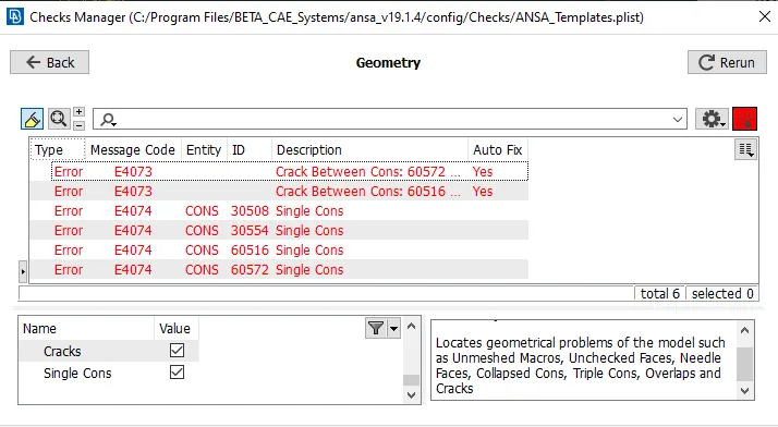
Fig: Error in Rearview Mirror Model
5. In The above window, an error has occurred in the given Geometry model. Check the error showing in the Model and fix the issue and clean up the Geometry.
6. While resolving the error, Right Click on the error which is going to resolve and click the fix option.

Fig: Eliminating the geometrical error
7. After Eliminating the geometrical error, and again Click Execute in the Checks Manager, and 100% Geometry Cleanup is to be verified.
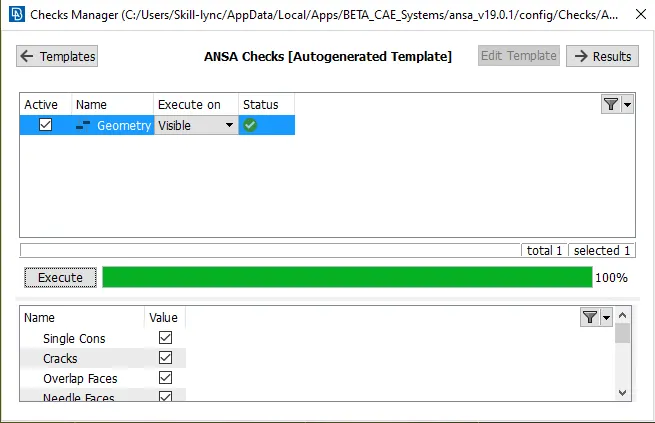
Fig: Eliminated Geometrical errors
B. Extracting Midsurface :
8. After geometry Cleanup and Mid-surface has to be created separately for each component which is less than 5mm.
9. Go to the Measure option to find the component which is less than 5mm.
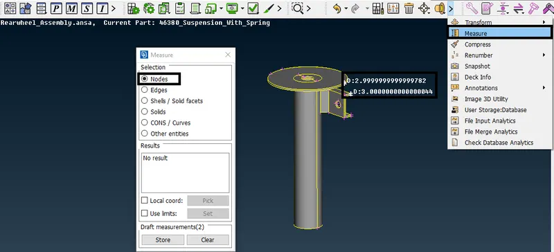
Fig: Measuring the Component
10. Go to Topo-->Faces-->Offset option and select the face and Create Midsurface.
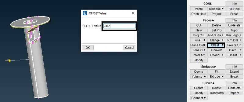
Fig: Extracting Midsurface
11. Finally mid surface has been created.
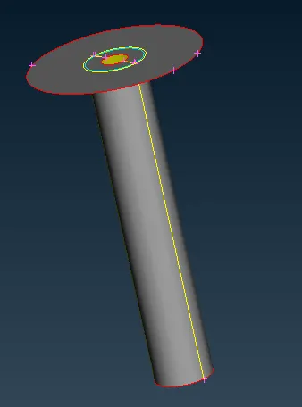
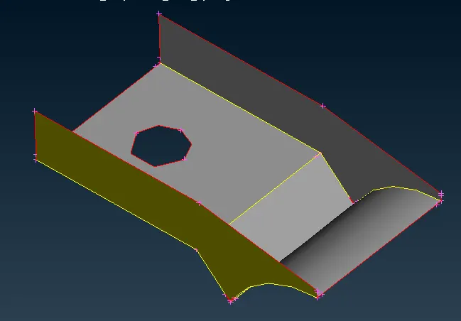
Fig: Midsurface for less than 5mm component
C. 2D Meshing :
12. Set the given Quality Criteria for the Component.
13. Go Utilities-->Quality Criteria-->Shells Option and assign the given Quality Criteria Values.
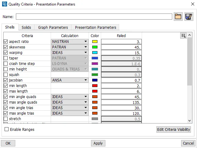
Fig: Quality Criteria
14. After assigning the Quality Criteria for the Component, Go to Utilities-->Mesh Parameters and Set Orthotria and assign the Target Length Value for TetraMeshing.
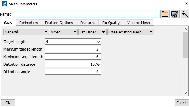
Fig: Mesh Parameters
15. Go to Mesh-->Perimeters--> Length Option and Select the Component to Mesh and enter the Value of Perimeter Length and Macro Length for Meshing.
16. Go to Mesh-->Mesh Generation Option and Select the Mesh type to mesh the component.
17. Select the Mesh type in the Mesh generation and Select the Faces to mesh and Mesh will be generated.
18. Use Shell Mesh-->Reconstruct option to rearrange the Mesh and Use Shell Mesh-->Smooth Option to arrange Mesh lines equally within the Selected Surface and solving the Quality criteria issues.
19. Use Grids-->Paste or Elements-->Split / Swap / Joint Option to eliminate or reduce the trias and get better mesh flow.
20. Check if there are any off elements is present and reduce the off elements and some areas of off elements will be acceptable.
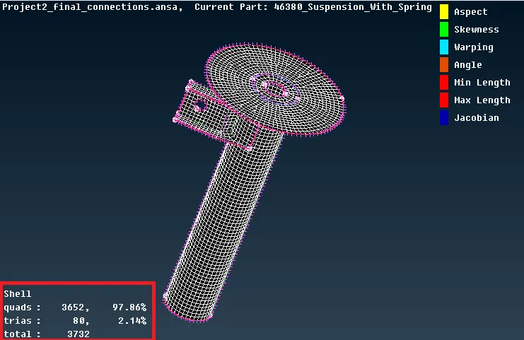
Fig: 2D Meshing with Quality Criteria
D. Volume Meshing (Tetra Mesh) :
21. Set the given Quality criteria and Mesh Parameter for Surface Meshing (Tetra mesh).
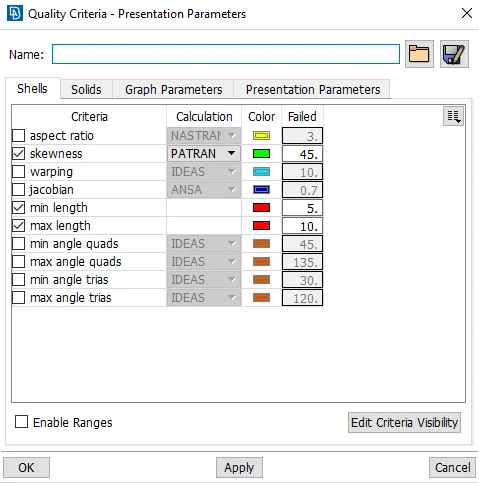
Fig: Quality Criteria for Surface Meshing
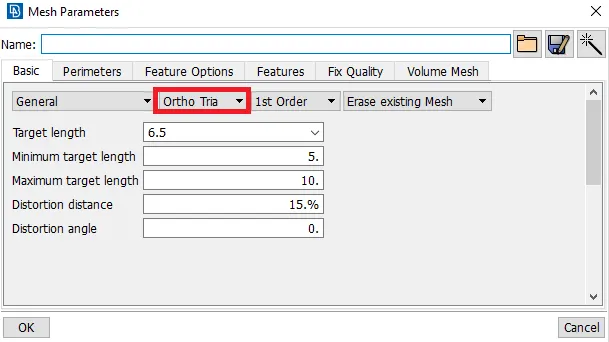
Fig: Mesh Parameters for Surface Meshing
22. Go to Mesh-->Perimeters--> Length Option and Select the Component to Mesh and enter the Value of Perimeter Length and Macro Length for Meshing.
23. Go to Mesh-->Mesh Generation Option and Select the Mesh type to mesh the component.
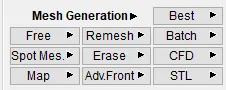
Fig: Mesh Generation Types
24. Select Spot Mesh with element type as ortho tria and select the fillet area and do tetra mesh.
25. Select Spot Mesh with element type as tria and select the normal Surface and do tetra mesh.
Fig: Surface Mesh using tria & ortho tria for Rim & Tyre
26. Change the Quality criteria & Mesh Parameters for Surface Meshing of Non-Uniform thickness components other than Tyre and Rim and Mesh the Component.
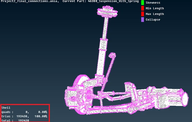
Fig: Surface Mesh using tria & ortho tria for other assembly Components
27. After Meshing for all surfaces, Check if there are any off elements is present and eliminate the off elements.
28. Go to Mesh-->Grids-->MV Free option and select the nodes and move in x,y,z, direction to clear the quality issue.
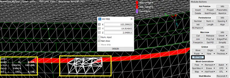
Fig: Eliminating off elements (Min & Max length)
29. Similarly eliminated all other off elements (Min & Max length) by using MV Free option.
30. For Volume Meshing, Go Utilities-->Quality Criteria-->Solids Option and assign the given Quality Criteria Values.
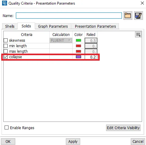
Fig: Volume Mesh Quality Criteria
31. After assigning the Quality criteria, Go to Volume Mesh-->Volumes--Define-->Manual option and Define the Volume.
32. Go to Volumes-->list option and check the defined volume.
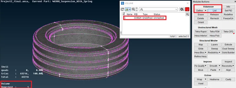
Fig: Defining a Volume
33. Go to Unstructured Mesh-->Tetra Rapid (or) Tetra FEM option and select the Volume and start meshing.
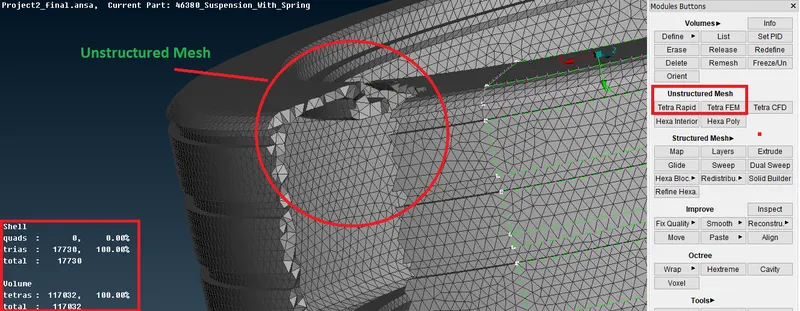
Fig: Unstructured Mesh using Tetra Rapid
34. Check if there are any off elements(collapse) is present and eliminate the off elements.
35. Go to Mesh-->Grids-->MV Free option and select the nodes and move in x,y,z, direction to clear the quality issue.
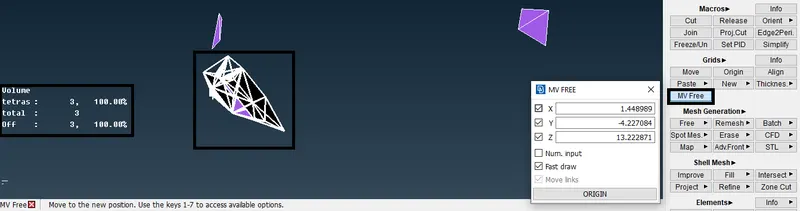
Fig: Eliminating off elements(collapse)
36. Similarly eliminated all other off elements (Min & Max length) by using MV Free option.
E. 1D Element Representation for Spring :
37. Go to Topo-->Curves-->Middle option and Select the CONS and create a curve.
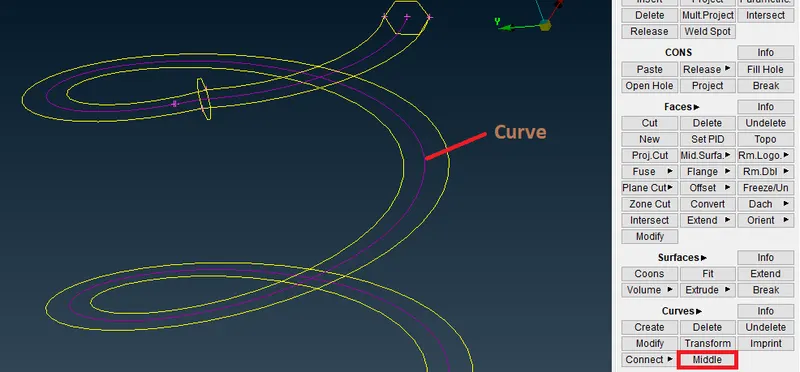
Fig: Creating a Curve
38. After Creating a curve, Go to NASTRAN DECk-->Elements-->CBAR option and Select the Curve to convert into a CBAR curve.
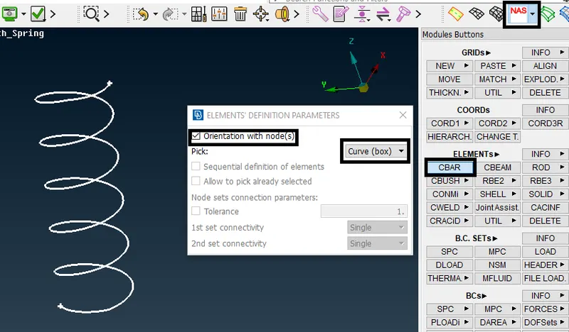
Fig: Selection of CBAR element and Curve
39. After selecting a curve, specify the element length and do a middle mouse click and define a PID by creating a new PID.
40. Define Area by giving a Radius of Spring, i.e. Cross Section radius of spring, assign the radius of spring and it will automatically calculate the remaining necessary things.
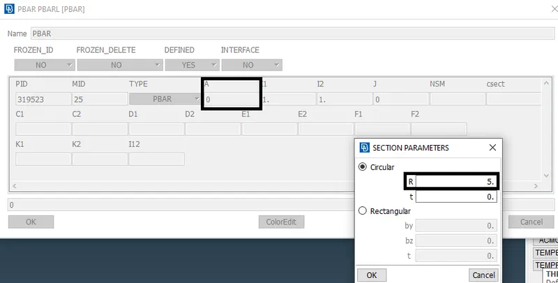
Fig: Defining Area and Specifying Radius
41. After specifying a radius, click ok and 1D Bar elements will be created.
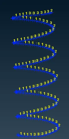
Fig: CBAR Elements
42. To see the representation of 1D Bar elements as 3D (solids), check the box of 1D detailed representation with the solid in quality parameters as shown in the below image.
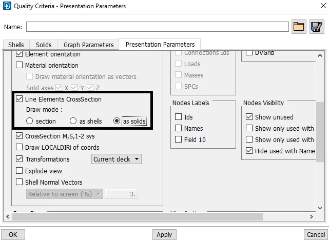
Fig: Presentation Parameters
43. Click on Apply and Ok, The 1D bar element will be represented as a solid element.
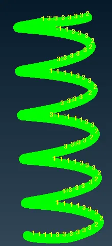
Fig: Representation of Spring with 1D elements
F. Performing Suitable Connections :
44. Connect the Rear suspension assembly by using rigid RBE2 connections.
45. Go to NASTRAN DECK-->Elements-->RBE2 option and select the nodes and Create an RBE2 Connection.
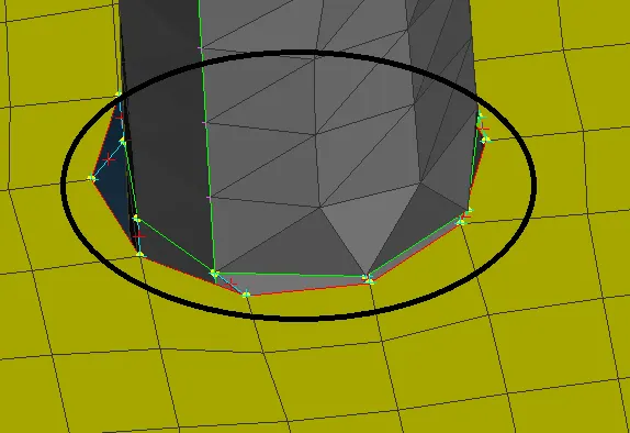
Fig: Two node RBE2 connection
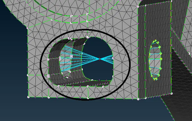
Fig: Cluster RBE2 Connection
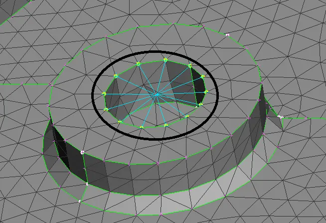
Fig: Spider RBE2 Connection
G. Symmetry half model to other side :
46. Go to Transform-->Copy option and Select the Entities and do middle mouse click button.
47. In the Copy Entities dialog box, Go to the symmetry tab and set Default Symmetry Plane and Click apply.
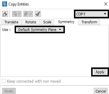
Fig: Specifying Symmetry operation
48. Finally click Finish and half model symmetry will be created.
H. Learning Outcomes :
49. Learned to Perform 2D Mesh and Volume Mesh (tetra mesh) rear suspension assembly model.
50. Learned to Create a CBAR element and performed RBE2 connection for rear suspension assembly model.
RESULT :
Checked for the geometrical errors & taken mid-surface for which is less than 5mm in rear suspension Assembly and 2D meshed with the given element Quality Criteria. Volume mesh has been created for rear suspension assembly with the given element quality criteria. Created CBAR Element for Springs and performed RBE2 connections and made symmetry operation for the Rear Suspension Assembly model.
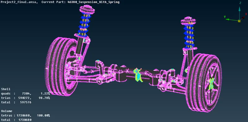
Fig: Rear Suspension Assembly Model Mesh with Suitable Connections