Project - 2 - Meshing on the suspension Assembly
Model Link: https://drive.google.com/file/d/1kF5OWeQO1ddVv_VjYd-lCi3jrcOyegQZ/view?usp=sharing
Aim-
For the given assembly, check for the geometrical errors and mesh with the given element Quality criteria. After meshing the component the thickness has to be assigned for mid surfaces. Use tetra elements to model non-uniform thickness components. Also use Appropriate connections to connect the component.
Given Data-
CAD
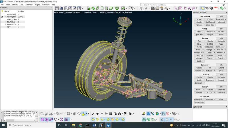
Quality Criterias
Quality Criteria for Surface Meshing of Tyre and Rim (Element type: Tria) :
|
S.No |
Quality Criteria |
Value |
|
1 |
Target/Average length |
6.5 |
|
2 |
Minimum Length |
5 |
|
3 |
Maximum Length |
10 |
|
4 |
Skewness |
45 |
Quality criteria for Surface Meshing of Non Uniform thickness components other than Tyre and Rim (Element type: Tria) :
|
S.No |
Quality Criteria |
Value |
|
1 |
Target/Average length |
4 |
|
2 |
Minimum Length |
2 |
|
3 |
Maximum Length |
6 |
|
4 |
Skewness |
45 |
Quality Criteria for Volume meshing of all Non Uniform thickness components (Element type: Tetra Elements):
|
S.No |
Quality Criteria |
Value |
|
1 |
Tet-collapse |
0.2 |
Quality criteria for Mid surfacing of Uniform thickness part which has thickness less than 5 mm (Element type: Mixed elements) :
|
S.No |
Quality Criteria |
Value |
|
1 |
Target/Average length |
4 |
|
2 |
Minimum Length |
2 |
|
3 |
Maximum Length |
6 |
|
4 |
Aspect |
3 |
|
5 |
Warpage |
15 |
|
6 |
Skewness |
45 |
|
7 |
Jacobian |
0.7 |
|
8 |
Minimum Quad Angle |
45 |
|
9 |
Maximum Quad Angle |
135 |
|
10 |
Minimum Tria Angle |
30 |
|
11 |
Maximum Tria Angle |
120 |
Methodology-
1) Topo And fixing geometrical errors
2) Geomertical Cleanups
3) Meshing Individual Components with their respective Quality Criterias and sloving quality issues
4) Volume mesh and solving the quality criterias
5) Releasing the FE from CAD and Volume
6) Providing Appropriate Connections
7) Mirroring the FE and Connecting Them
1) Topo And fixing geometrical errors
After importing the cad into ANSA we give it a quick TOPO by using TOPO>>FACES>>TOPO and to better the quality we go to MESH MODULE>>PERMETERS>>LENGTH and give the tyre and rim a perimeter length of 6.5 and the reamining components as 4.
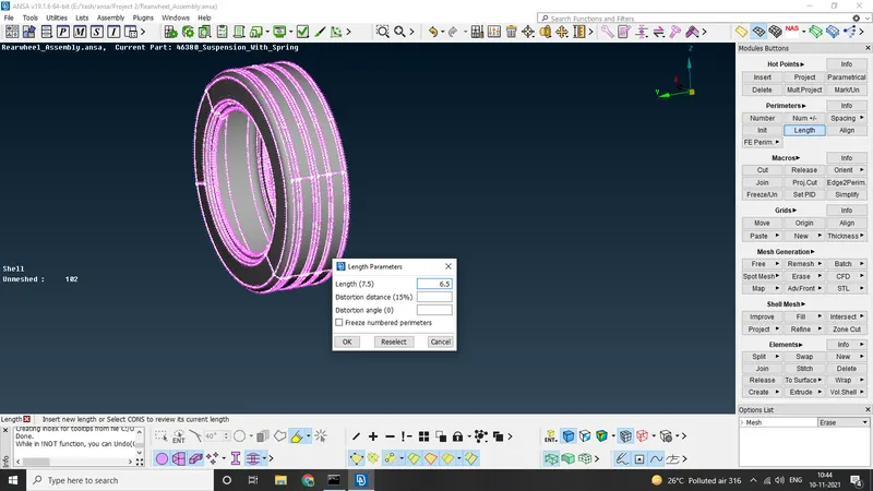
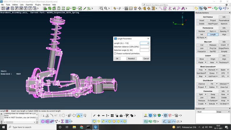
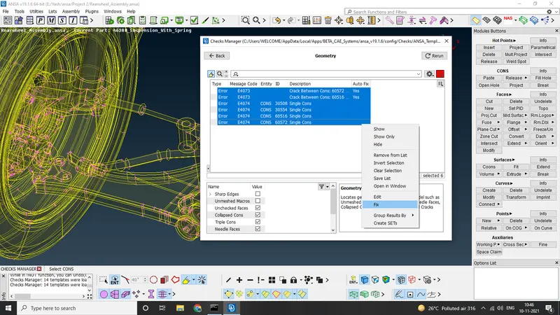
now we use CHECKS>>GEOMETRY here all the errors will be seen, before executing it make sure we tick all the options except unmeshed macros and sharp edges
here we found few erros which were automatically fixed by FIX command, to do this select all the errors>>right click>>FIX
2) Geomertical Cleanups
Now there are many features that are a bit too complex to mesh, or they will through quality issues when we probide quality criterias so we use diffrent ways to simplify them such as TOPO>>FACES>>CUT/NEW/DELETE, etc
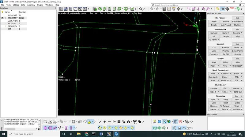
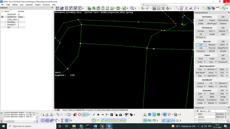
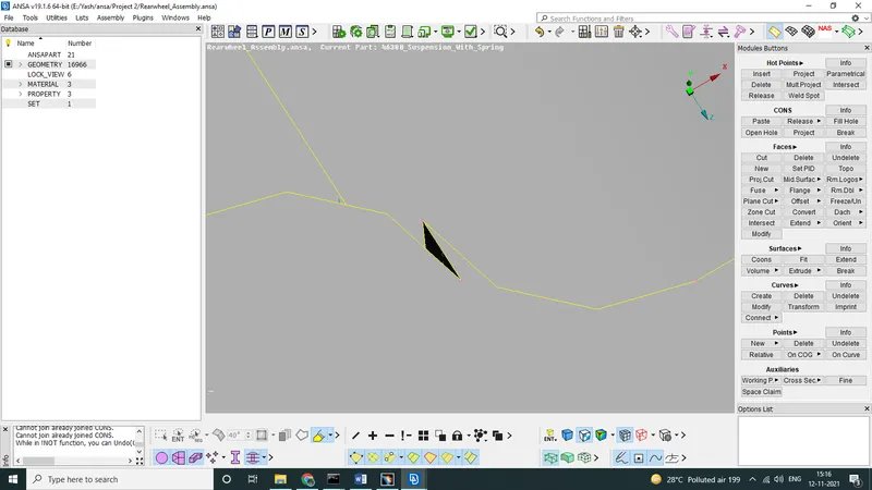
3) Meshing Individual Components with their respective Quality Criterias and sloving quality issues
Now we seperate the individual parts from each other by using !NOT>>PID & PID Region
First we go for tyre and rim , here we assign the quality criterias accordingly by presssing F11 and give average length , minimum and maximum lenght and type of elements as tri to MESH PARAMETERS and reslove any quality issues by use of MESH MODULE>>MESH GENERATION>>SPOT MESH/REMESH, MESH MODULE>>GRIDS>>MV FREE/MV SURF/MV HOLE, MESH MODULE>>SHELL MESH>>RECONSTRUCT>>SMOOTH, MESH MODULE>>ELEMENTS>>SPLIT
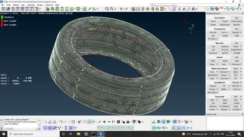
For the remaining parts we changed the quality criterias and used BATCH MESH for more quicker results
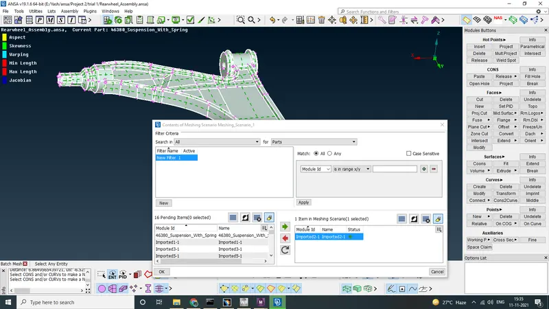
here most of the features were capturea as we already simplified them in step 2, errors were fixed as above methods
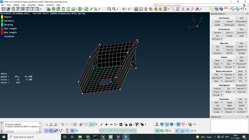
now there were only 2 components with uniform thickness less then 5 mm , so i used manual offset for mid surfacing them and again changed the quality criterias accordingly.
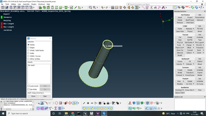
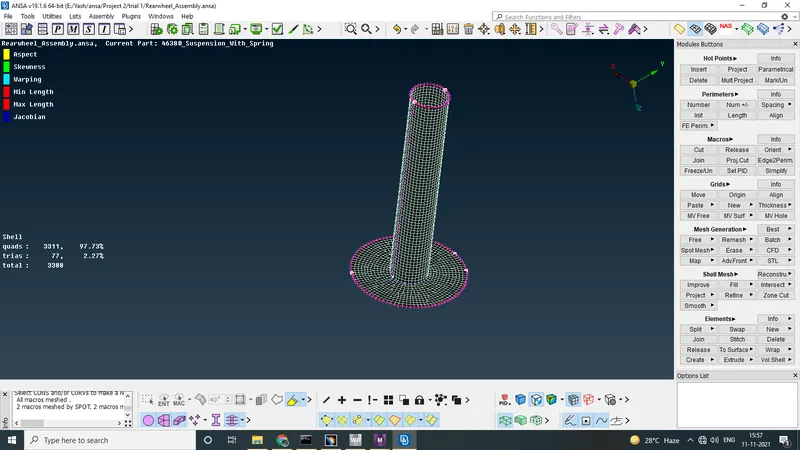
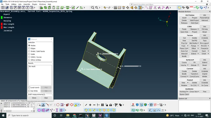
4) Volume mesh and solving the quality criterias
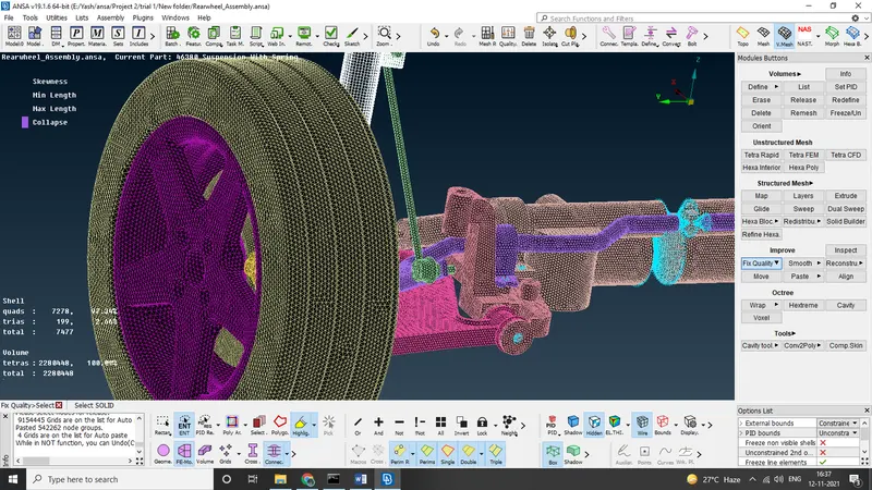
now since our meshing is donw we move to volume mesh module, here we first define the components by VOLUME MESH MODULE>>VOLUME>>DEFINE>>AUTO DETECT>>VISIBLE
and all the component will we visible in the VOLUME MESH MODULE>>VOLUME>>LISTS
now here in LISTS we select all the components and RIGHT CLICK>>REMESH>>TETRA FEM and all of our components in that list are now remeshed
here again we give quality criteria as tet collapse=0.2
if there are any quality issues we can solve them by using VOLUME MESHH MODULE>>IMPROVE>>FIX QUALITY >>SELECT and select the area of error
5) Releasing the FE from CAD and Volume
Now as we know that the mesh generated here is still associated with the cad, so first we have to release it by switching of CAD and FE both , only volume is visible, now use VOLUME MESH MODULE>>VOLUME>>RELEASE
now if we only turn on FE we can see the solid mesh , now go to NASTRAN DECK>>GRIDS>>RELEASE>>NODES and use this option on FE only
now go to MESH MODULE>>HOT POINTS>>DELETE and delete all the hot points from CAD only by turning of FE
now do the same for FE only by turning off the CAD
Now go to NASTRAN DECK>>PASTE>>AUTO>>VISIBLE use this on FE only and on middle-click confirmation, our solid mesh is now completely independent from CAD,
But there is still 2 more components that we need to release, for those go to MESH MODULE>>ELEMENTS>>RELEASE and use this on both PSHELLS that we created as mid surfaces.
6) Providing Appropriate Connections
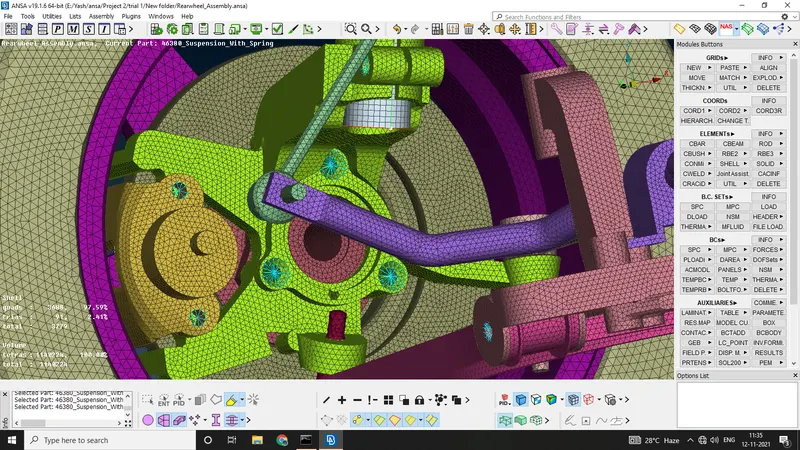
Now there are several nut and bolt connection and weld connections, we deploy them by using NASTRSAN DECK>>ELEMENTS>>RBE2>>MANY NODES/2 NODES,
for hinges we use RBE2>>2 Nodes on 2 master nodes of connecting holes
for 2 surfaces to be bolted together use the same
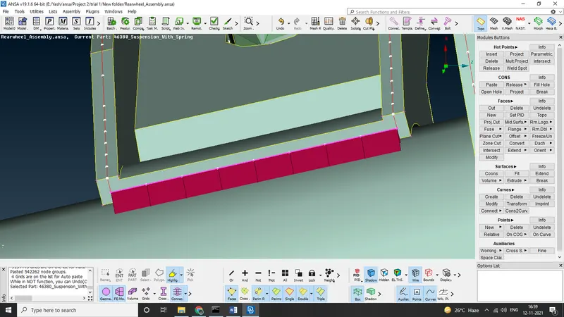
for seam weld connections we use TOPO>>CURVES>>CONS2CURVES to create a curve and use CONNECT>>MULTI to connect the whole curve, now we use CONVERT>>CURVES>>SEAM LINE to convert the curve into a seam line,
now we go to CONNECTION MANAGER and select the seam line and middle click, here we define P1 and P2 by double clicking on them then F1 now we select the part that we want as P1 and ENTER do the same for P2, here both the surfaces are parallel to each other so we would go for OVERLAP PSHELL, here we assign the search distance between them, width of the weld, and no. of steps,now we go to WELD PID and press SHIFT + ? to assign new weld PID
7) Mirroring the FE and Connecting Them
Now to Mirror the FE we go to TRANSFORM>>COPY>>SELECT THE WHOLE FE>>SYMMETRY>>DEFAULT SYMMETRY PLANE
now we connect these two together by RBE2>>MANY NODES
CONCLUSION-
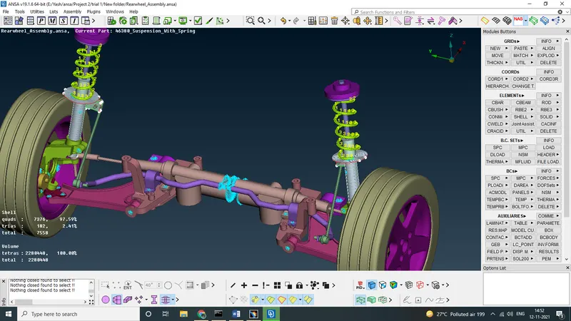
The rear sub-assembly of suspension has several different parts with non-uniform thickness mostly, most of them were mesh by using batch mesh but a few manually meshed for more accuracy, quality criteria were followed accordingly, connections were given where ever necessary.
Model Link: https://drive.google.com/file/d/1kF5OWeQO1ddVv_VjYd-lCi3jrcOyegQZ/view?usp=sharing